

Optimizing Battery Isolator Installation to Minimize Voltage Drops
MAY 29, 20269 MIN READ
Generate Your Research Report Instantly with AI Agent
PatSnap Eureka helps you evaluate technical feasibility & market potential.
Battery Isolator Technology Background and Optimization Goals
Battery isolator technology emerged in the mid-20th century as automotive and marine electrical systems became increasingly complex. Initially developed for dual-battery systems in commercial vehicles, these devices prevent battery discharge between primary and auxiliary circuits while allowing simultaneous charging. Early mechanical isolators used solenoid-based switching mechanisms, which gradually evolved into semiconductor-based solutions offering improved reliability and reduced maintenance requirements.
The fundamental principle of battery isolation involves creating a unidirectional current path that permits charging current flow while blocking reverse discharge. Traditional diode-based isolators, while simple and cost-effective, introduced inherent voltage drops of 0.6-0.7 volts per junction. This voltage loss became a critical limitation as electrical systems demanded higher efficiency and precision voltage regulation.
Modern battery isolator technology has progressed through several evolutionary phases. Silicon diode isolators dominated early applications but suffered from significant voltage drops and heat generation. The introduction of Schottky diodes reduced forward voltage drop to 0.3-0.4 volts, improving efficiency substantially. Subsequently, MOSFET-based isolators emerged, offering near-zero voltage drop characteristics through active switching control, representing a paradigm shift in isolator design philosophy.
Contemporary applications span diverse sectors including automotive, marine, recreational vehicles, telecommunications, and renewable energy systems. Each application presents unique challenges regarding current capacity, environmental conditions, and voltage drop tolerance. Marine applications particularly emphasize corrosion resistance and reliability, while automotive systems prioritize compact packaging and thermal management.
The primary optimization goal centers on minimizing voltage drop while maintaining reliable isolation functionality. Voltage drop reduction directly impacts charging efficiency, battery lifespan, and system performance. Secondary objectives include thermal management, installation flexibility, cost optimization, and long-term reliability. Advanced isolator systems now target voltage drops below 0.1 volts under normal operating conditions.
Installation optimization encompasses multiple factors including cable routing, connection quality, thermal considerations, and electromagnetic compatibility. Proper installation techniques can reduce total system voltage drop by 30-50% compared to suboptimal configurations. This involves strategic placement, appropriate wire gauge selection, and minimizing connection resistance through proper termination methods.
Future development trajectories focus on intelligent isolator systems incorporating microprocessor control, adaptive switching algorithms, and integrated monitoring capabilities. These smart isolators promise dynamic optimization based on real-time operating conditions, potentially achieving theoretical minimum voltage drops while providing enhanced diagnostic capabilities and predictive maintenance features.
Market Demand for Efficient Battery Management Systems
The global battery management systems market is experiencing unprecedented growth driven by the rapid expansion of electric vehicles, renewable energy storage, and portable electronics. This surge in demand has created a critical need for efficient battery management solutions that can maximize energy utilization while ensuring system reliability and longevity.
Electric vehicle manufacturers represent the largest segment driving demand for advanced battery management technologies. As automotive companies strive to extend driving range and reduce charging times, the optimization of every component in the electrical system becomes paramount. Battery isolators play a crucial role in this ecosystem, and minimizing voltage drops has become a key performance indicator that directly impacts vehicle efficiency and consumer satisfaction.
The renewable energy sector presents another significant market opportunity for optimized battery isolator solutions. Solar and wind energy installations increasingly rely on sophisticated battery storage systems to manage intermittent power generation. These applications demand highly efficient power management components that can minimize energy losses during charging and discharging cycles, making voltage drop optimization a critical technical requirement.
Industrial and marine applications constitute a substantial market segment where dual battery systems are essential for operational safety and reliability. In these environments, battery isolators must maintain optimal performance under harsh conditions while ensuring minimal power loss between battery banks. The growing emphasis on operational efficiency and fuel cost reduction has intensified demand for advanced isolator technologies.
Consumer electronics and recreational vehicle markets are also driving innovation in battery management systems. As devices become more power-hungry and users expect longer battery life, manufacturers are seeking every possible efficiency gain. Optimized battery isolator installation techniques that minimize voltage drops directly translate to improved user experience and competitive advantage.
The market demand is further amplified by increasingly stringent energy efficiency regulations across various industries. Government mandates for reduced emissions and improved energy utilization are pushing manufacturers to adopt more sophisticated battery management solutions, creating sustained demand for optimized isolator technologies and installation methodologies.
Current State and Voltage Drop Challenges in Battery Isolators
Battery isolators currently face significant voltage drop challenges that directly impact system efficiency and performance across various applications. Modern battery isolator technologies primarily include diode-based isolators, solenoid-based systems, and solid-state isolators, each presenting distinct voltage drop characteristics. Diode isolators typically exhibit voltage drops ranging from 0.6V to 1.2V under normal operating conditions, while solenoid-based systems can achieve near-zero voltage drops when properly engaged but suffer from mechanical reliability issues.
The automotive and marine industries represent the largest application segments for battery isolators, where voltage drop optimization is critical for maintaining auxiliary battery charging efficiency. In recreational vehicles and marine vessels, voltage drops exceeding 0.8V can result in inadequate charging of house batteries, leading to premature battery failure and reduced system reliability. Commercial vehicle applications face similar challenges, particularly in heavy-duty trucks where multiple battery banks require isolation while maintaining optimal charging performance.
Current installation practices often overlook critical factors contributing to voltage drops, including cable sizing, connection quality, and thermal management. Industry surveys indicate that approximately 60% of battery isolator installations suffer from suboptimal voltage performance due to inadequate wire gauge selection and poor connection techniques. The resistance introduced by undersized conductors can add an additional 0.2V to 0.5V drop beyond the isolator's inherent losses.
Temperature effects significantly compound voltage drop challenges in battery isolator systems. Semiconductor-based isolators experience increased forward voltage drops at elevated temperatures, with some devices showing 20-30% performance degradation at temperatures exceeding 85°C. This thermal sensitivity necessitates careful consideration of installation location and heat dissipation strategies to maintain optimal performance.
Emerging solid-state isolator technologies utilizing MOSFET switching architectures show promise for addressing voltage drop limitations. These advanced systems can achieve voltage drops as low as 0.1V to 0.3V while providing enhanced control capabilities and diagnostic features. However, their higher cost and complexity present adoption barriers in price-sensitive applications.
The integration of smart charging systems and battery management technologies has introduced new requirements for low-voltage-drop isolators. Modern lithium battery systems demand precise voltage control, making traditional high-drop isolator solutions increasingly inadequate for next-generation energy storage applications.
Existing Solutions for Minimizing Voltage Drops in Isolators
01 Diode-based battery isolation circuits
Battery isolator systems utilize diode configurations to prevent reverse current flow between multiple batteries while allowing charging from a common source. These circuits help minimize voltage drops through optimized diode selection and arrangement, ensuring efficient power distribution in multi-battery systems.- Diode-based battery isolation circuits: Battery isolator systems utilize diode configurations to prevent reverse current flow between multiple batteries while allowing charging from a common source. These circuits help minimize voltage drops through optimized diode selection and arrangement, ensuring efficient power distribution in multi-battery systems.
- Electronic switching isolator designs: Advanced electronic switching circuits replace traditional diode isolators to reduce voltage drops significantly. These systems use semiconductor switches and control circuits to provide near-zero voltage drop isolation while maintaining proper battery separation and charging functionality.
- Voltage drop compensation mechanisms: Compensation circuits are implemented to counteract inherent voltage drops in battery isolator systems. These mechanisms actively monitor and adjust voltage levels to ensure proper battery charging despite losses in the isolation circuitry, maintaining optimal battery performance.
- Smart battery management integration: Modern battery isolator systems incorporate intelligent management features that monitor voltage drops and automatically adjust isolation parameters. These systems optimize charging efficiency while protecting batteries from overcharge and reverse discharge conditions.
- Multi-battery charging optimization: Specialized circuits designed for multi-battery applications focus on minimizing voltage drops across isolation barriers while ensuring balanced charging. These systems employ various techniques to maintain charging efficiency across multiple battery banks in automotive and marine applications.
02 Solid-state switching isolators
Advanced battery isolators employ solid-state switching devices such as MOSFETs or transistors to achieve lower voltage drops compared to traditional diode-based systems. These electronic switches can be controlled to minimize conduction losses and improve overall system efficiency.Expand Specific Solutions03 Voltage drop compensation techniques
Compensation methods are implemented to counteract inherent voltage drops in battery isolator circuits. These techniques include voltage sensing feedback loops, boost circuits, and adaptive control systems that maintain proper charging voltages across isolated battery banks.Expand Specific Solutions04 Temperature-compensated isolator designs
Battery isolator systems incorporate temperature compensation mechanisms to address voltage drop variations caused by thermal effects on semiconductor devices. These designs ensure consistent performance across different operating temperature ranges and environmental conditions.Expand Specific Solutions05 Multi-battery management with reduced losses
Integrated battery management systems feature isolator circuits designed to minimize voltage drops while managing multiple battery banks. These systems optimize power distribution, prevent cross-discharge, and maintain individual battery health through intelligent switching and monitoring capabilities.Expand Specific Solutions
Key Players in Battery Isolator and Power Management Industry
The battery isolator optimization market represents a mature yet evolving segment within the broader automotive electrical systems industry, driven by increasing electrification demands across transportation sectors. The market demonstrates steady growth as electric and hybrid vehicles proliferate, creating substantial opportunities for voltage drop minimization technologies. Key players exhibit varying technological maturity levels, with established battery manufacturers like Contemporary Amperex Technology, LG Energy Solution, Samsung SDI, and BYD leading advanced battery management solutions, while component specialists such as Panasonic Holdings, Murata Manufacturing, and Celgard provide critical supporting technologies including separators and electronic components. Traditional automotive suppliers like YAZAKI Corp focus on wire harness integration, and simulation companies like ANSYS offer optimization tools. The competitive landscape spans from highly mature lithium-ion battery technologies to emerging power management systems, with Asian manufacturers particularly dominant in battery cell production while specialized component providers maintain strong positions in materials and electronic control systems.
Panasonic Holdings Corp.
Technical Solution: Panasonic implements battery isolator optimization through their cylindrical cell technology combined with proprietary busbar designs that minimize electrical path resistance. Their approach includes nickel-plated steel isolator housings with precision-machined contact surfaces to ensure consistent electrical connectivity. The company's installation methodology incorporates ultrasonic welding techniques for permanent connections and mechanical isolators with spring-loaded contacts for serviceable applications. Panasonic's thermal analysis ensures isolator placement considers heat dissipation patterns to prevent performance degradation over the battery lifecycle.
Strengths: Decades of battery technology experience, robust quality control systems. Weaknesses: Traditional cylindrical format limitations, slower adaptation to newer architectures.
Contemporary Amperex Technology Co., Ltd.
Technical Solution: CATL develops optimized battery isolator solutions through their CTP (Cell-to-Pack) technology that eliminates traditional module-level isolators, reducing voltage drop points by up to 40%. Their Qilin battery technology incorporates micro-isolator arrays with ultra-low resistance materials including silver-copper alloy contacts. The installation process utilizes precision robotic assembly with real-time resistance monitoring to ensure each connection meets specifications below 0.05 milliohms. CATL's thermal management integration ensures isolator performance stability across operating temperature ranges from -30°C to 60°C.
Strengths: Industry-leading energy density optimization, cost-effective manufacturing scale. Weaknesses: Relatively newer technology with limited long-term field data.
Core Innovations in Low-Drop Battery Isolation Technologies
An improved battery isolator unit
PatentActiveAU2009243458B2
Innovation
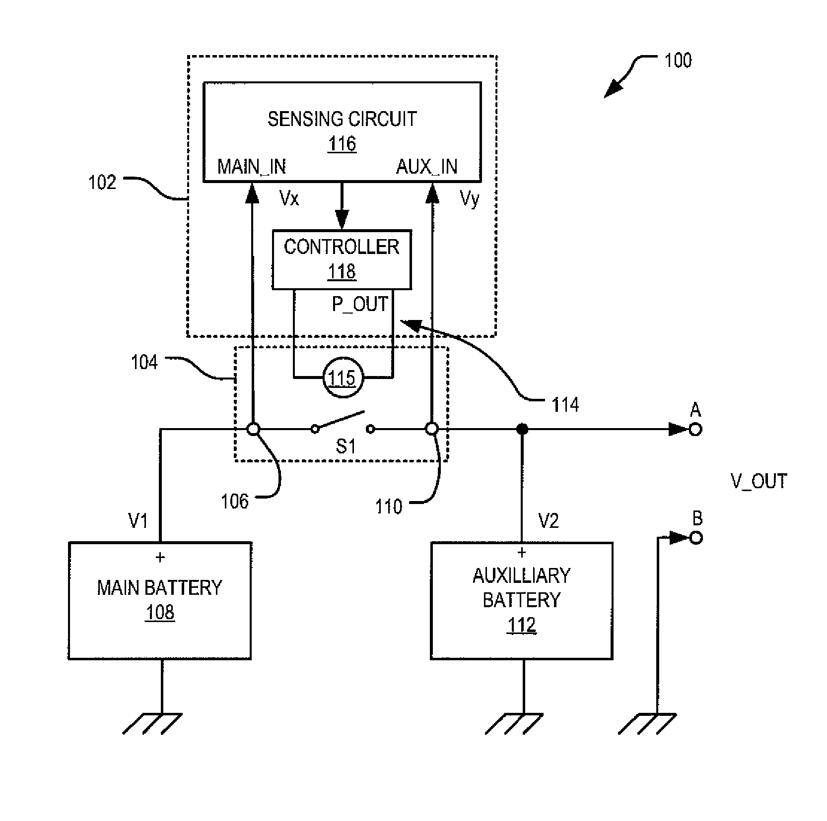
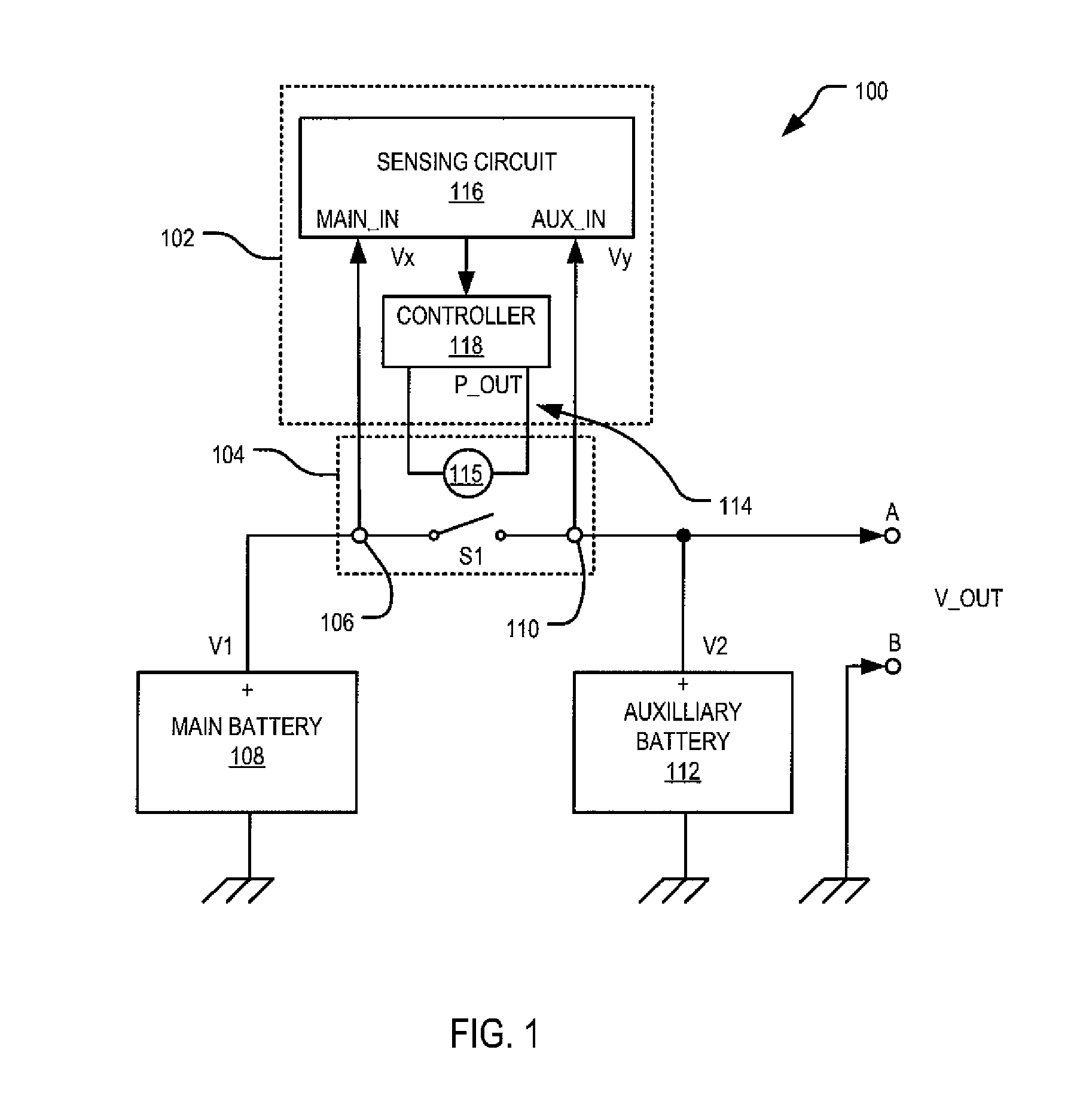
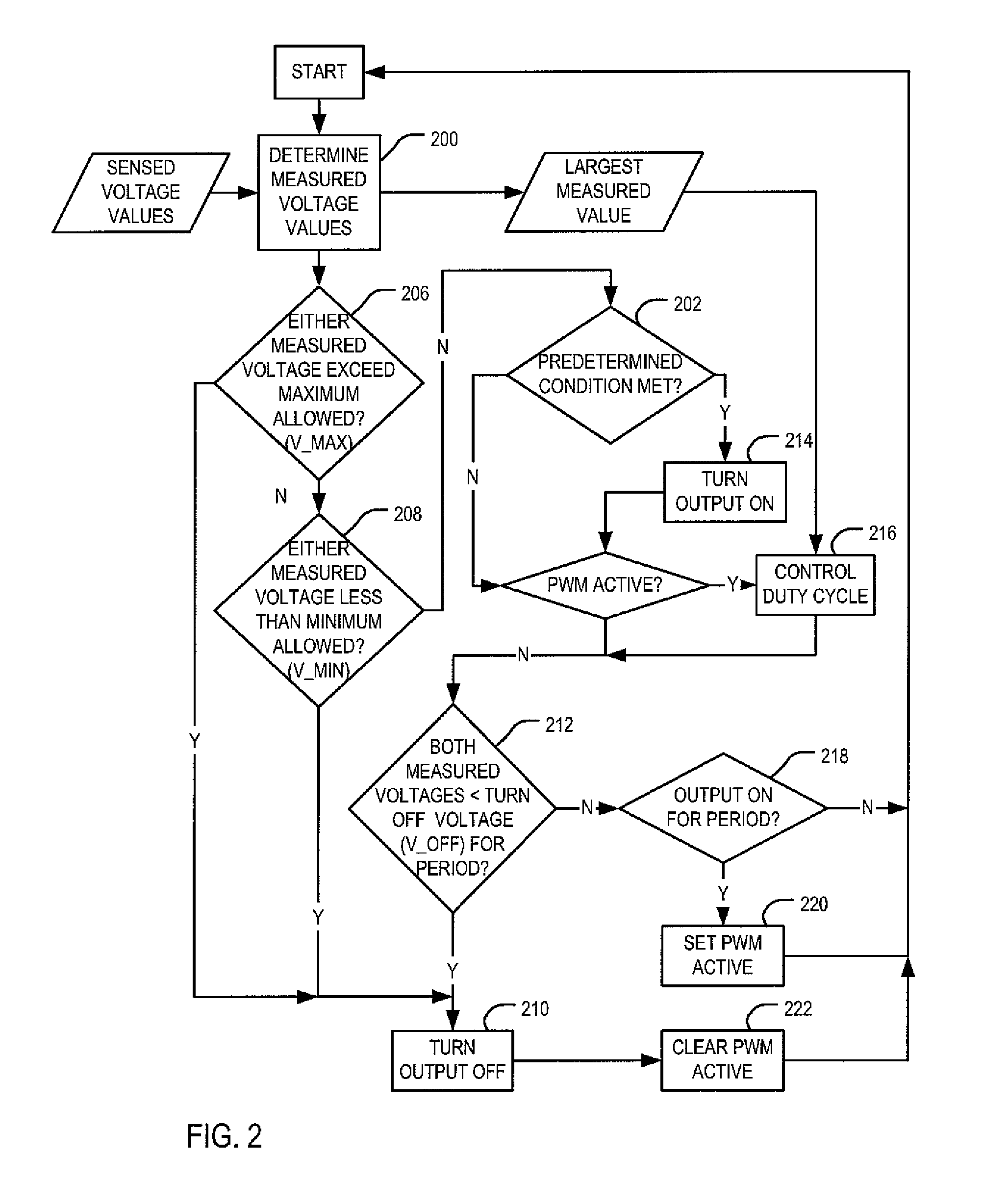
- A battery isolator unit with a sensing circuit and switch controller that periodically determines terminal voltage values of main and auxiliary batteries, using statistical means to control a switching mechanism, reducing the power needed to maintain the switch in a closed position through pulse width modulation of the control signal, thereby minimizing self-heating and power consumption.


Battery isolator unit
PatentActiveUS8390145B2
Innovation
- A battery isolator unit with a sensing circuit that periodically determines terminal voltage values of main and auxiliary batteries, and a switch controller that adjusts the bias of a switching element based on the difference between these values, using a pulse width modulated signal to minimize power consumption and reduce self-heating by optimizing the energization of the switching element.

Installation Standards and Safety Regulations for Battery Systems
Battery isolator installation must comply with established industry standards to ensure optimal performance and safety. The National Electrical Code (NEC) Article 480 provides fundamental guidelines for battery system installations, specifying minimum clearances, ventilation requirements, and conductor sizing. Marine applications follow additional standards such as ABYC E-11, which addresses specific challenges in marine environments including corrosion resistance and vibration tolerance.
Installation standards emphasize proper conductor sizing to minimize voltage drops across isolator connections. The American Wire Gauge (AWG) specifications require conductors to be sized for no more than 3% voltage drop under maximum load conditions. This necessitates careful calculation of wire length, current capacity, and ambient temperature factors. Standards also mandate the use of tinned copper conductors in marine applications to prevent galvanic corrosion.
Safety regulations require comprehensive protection mechanisms for battery isolator systems. Overcurrent protection devices must be installed within 7 inches of the battery positive terminal, as specified by USCG regulations for marine applications. Ground fault protection is mandatory in systems exceeding 50 volts, with automatic disconnection capabilities required for fault conditions exceeding 5 milliamperes.
Thermal management regulations establish maximum operating temperatures for isolator components. UL 1741 standards specify that isolators must operate safely at temperatures up to 60°C ambient, with appropriate derating factors applied beyond this threshold. Ventilation requirements ensure adequate heat dissipation, particularly critical for high-current applications where voltage drop optimization demands maximum current handling capacity.
Installation procedures must follow manufacturer specifications while adhering to regulatory frameworks. Torque specifications for terminal connections typically range from 35-50 foot-pounds for large isolators, ensuring optimal electrical contact while preventing mechanical stress. Regular inspection schedules, as mandated by Coast Guard regulations, require annual testing of isolator functionality and connection integrity to maintain compliance and performance standards.
Thermal Management Considerations in Battery Isolator Design
Thermal management represents a critical design consideration in battery isolator systems, as excessive heat generation directly contributes to voltage drops and system inefficiency. The relationship between temperature and electrical resistance in semiconductor-based isolators creates a cascading effect where poor thermal design leads to increased resistance, higher voltage drops, and further heat generation.
Modern battery isolators, particularly MOSFET-based designs, exhibit temperature-dependent characteristics that significantly impact their voltage drop performance. As junction temperatures rise above optimal operating ranges, the on-resistance of power MOSFETs increases substantially, creating additional voltage drops across the isolator circuit. This thermal-electrical interdependency necessitates sophisticated thermal management strategies to maintain consistent low-voltage-drop performance across varying operational conditions.
Heat dissipation mechanisms in battery isolator design encompass both passive and active cooling approaches. Passive thermal management relies on optimized heat sink design, thermal interface materials, and strategic component placement to maximize natural convection and conduction pathways. Advanced thermal interface materials with high thermal conductivity coefficients enable efficient heat transfer from semiconductor junctions to heat dissipation surfaces.
Active thermal management solutions incorporate forced air cooling, liquid cooling systems, or thermoelectric cooling elements for high-power applications. These systems maintain junction temperatures within optimal ranges, ensuring consistent low-resistance operation and minimal voltage drops. Temperature monitoring circuits with feedback control mechanisms enable dynamic thermal management, adjusting cooling intensity based on real-time thermal conditions.
Thermal design optimization involves careful consideration of power density distribution, component spacing, and airflow patterns within isolator assemblies. Computational fluid dynamics modeling helps predict thermal behavior and identify potential hot spots that could compromise voltage drop performance. Strategic placement of high-power components and implementation of thermal spreading techniques distribute heat loads more effectively across available dissipation surfaces.
Environmental thermal considerations include ambient temperature variations, enclosure thermal characteristics, and installation proximity to other heat-generating components. Robust thermal design ensures consistent isolator performance across specified temperature ranges while maintaining safety margins to prevent thermal runaway conditions that could catastrophically increase voltage drops.
Unlock deeper insights with PatSnap Eureka Quick Research — get a full tech report to explore trends and direct your research. Try now!
Generate Your Research Report Instantly with AI Agent
Supercharge your innovation with PatSnap Eureka AI Agent Platform!