
C-Shaped Rail Connecting Element for Vibration Damping
Find Innovative SolutionsGenerate Solutions
Solution Overview
Problem
Existing connecting elements for rail vehicles face challenges such as restricted constructive freedom due to incompatible cross-sections, increased overall height, and vulnerability to cracking or breaking under load changes, which affect their service life and ability to absorb both compressive and tensile forces effectively.
Innovation Solution
A connecting element with a C-shaped retaining rail and a plate-shaped element embedded in rubber-elastic damping material, where the plate-shaped element's bores are within the outer boundary of the retaining rail, preventing moments that could cause cracking and allowing for compact design and efficient force distribution.
Engineering Contradictions & Design Principles
Engineering Contradiction Analysis
1Area of stationary object
If the plate-shaped element protrudes beyond the outer boundary of the retaining rail in the longitudinal direction, then it provides sufficient attachment surface area, but it increases the overall length and creates moments that can cause cracking or breaking under load changes
Solution Approach 1:
The patent repositions the attachment bores from the longitudinal ends of the plate-shaped element to its transverse edges, utilizing the transverse dimension instead of the longitudinal dimension for attachment. This dimensional shift allows sufficient attachment surface area without increasing the overall length in the longitudinal direction, thereby avoiding the creation of problematic moments under load changes.
2Adaptability or versatility
If the C-shaped retaining rail has interruptions along its length to accommodate other components, then it allows for component introduction and connection, but it increases the device complexity and restricts constructive freedom
Solution Approach 1:
The patent designs the C-shaped retaining rail with a continuous structure that serves multiple functions: it provides structural support, accommodates the plate-shaped element through its gap, and allows component introduction through its open side. This continuous multi-functional design eliminates the need for interruptions while maintaining adaptability, thereby reducing structural complexity.
3Length of moving object
If the connecting element uses a compact design with the plate-shaped element within the retaining rail boundary, then it reduces overall height and saves space, but it requires efficient force distribution to handle both tensile and compressive forces
Solution Approach 1:
The patent positions the attachment bores at the transverse edges of the plate-shaped element, which are the regions experiencing different stress distributions under tensile and compressive loads. This local optimization of bore placement ensures efficient force distribution at critical locations, enabling the compact design to handle both tensile and compressive forces effectively without increasing overall height.
Applied Scientific Principles
This section explains which scientific principles are used to turn an abstract innovation direction into a practical engineering solution.
Function Achieved in This Case
The solution provides a compact, durable, and space-saving vibration-damping and sound-damping connection that reduces the risk of cracking, supports both tensile and compressive forces, and allows for versatile installation and adaptation to different loads and applications.
Implementation Method 1
a rubber-elastic damping material which is arranged at least in sections between the retaining rail and the plate-shaped element and into which the plate-shaped element is embedded at least with two of its edges
Implementation Method 2
vibration-damping and sound-damping connection between two components
Data Source
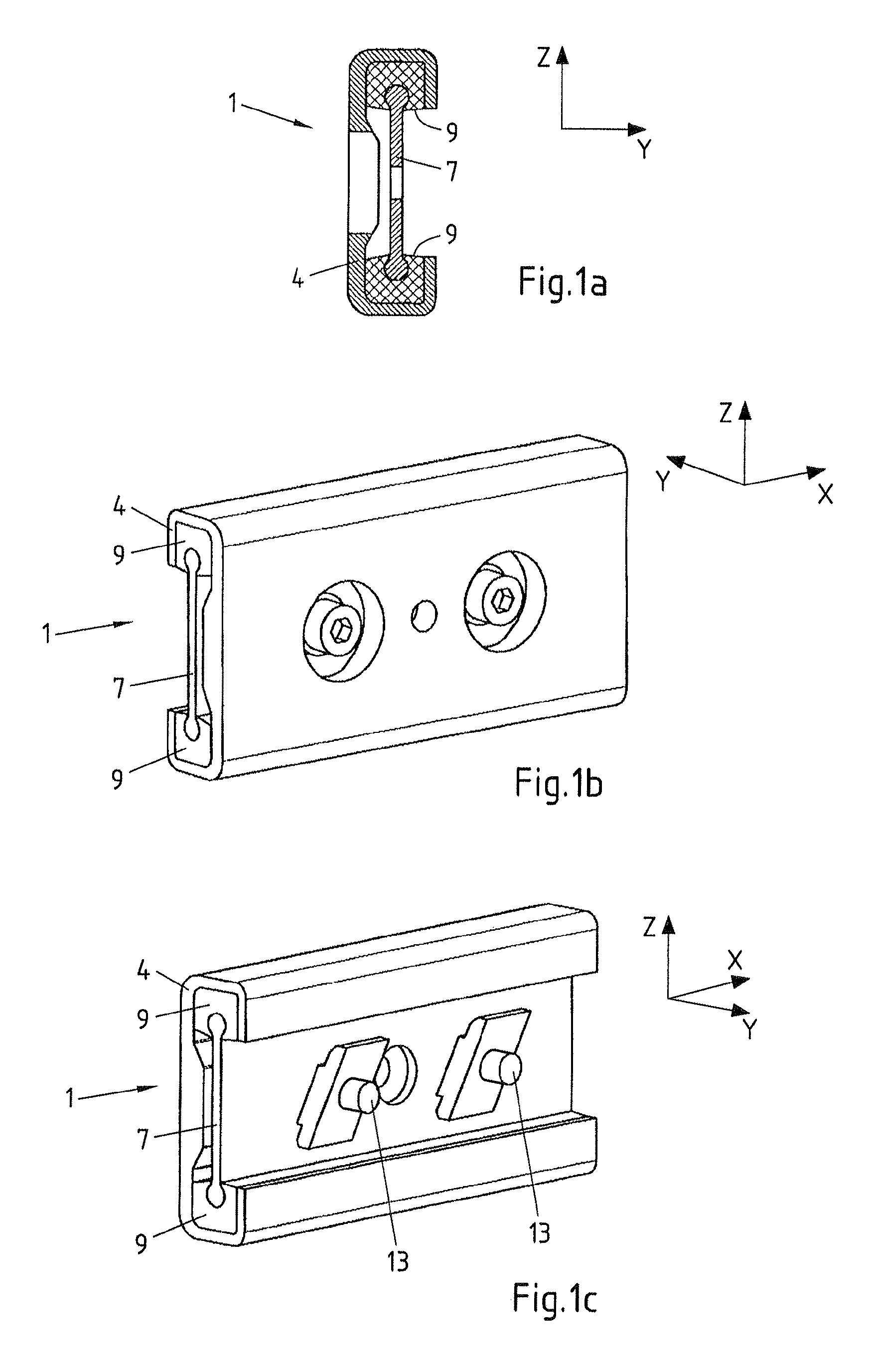 Figure 1a~1c
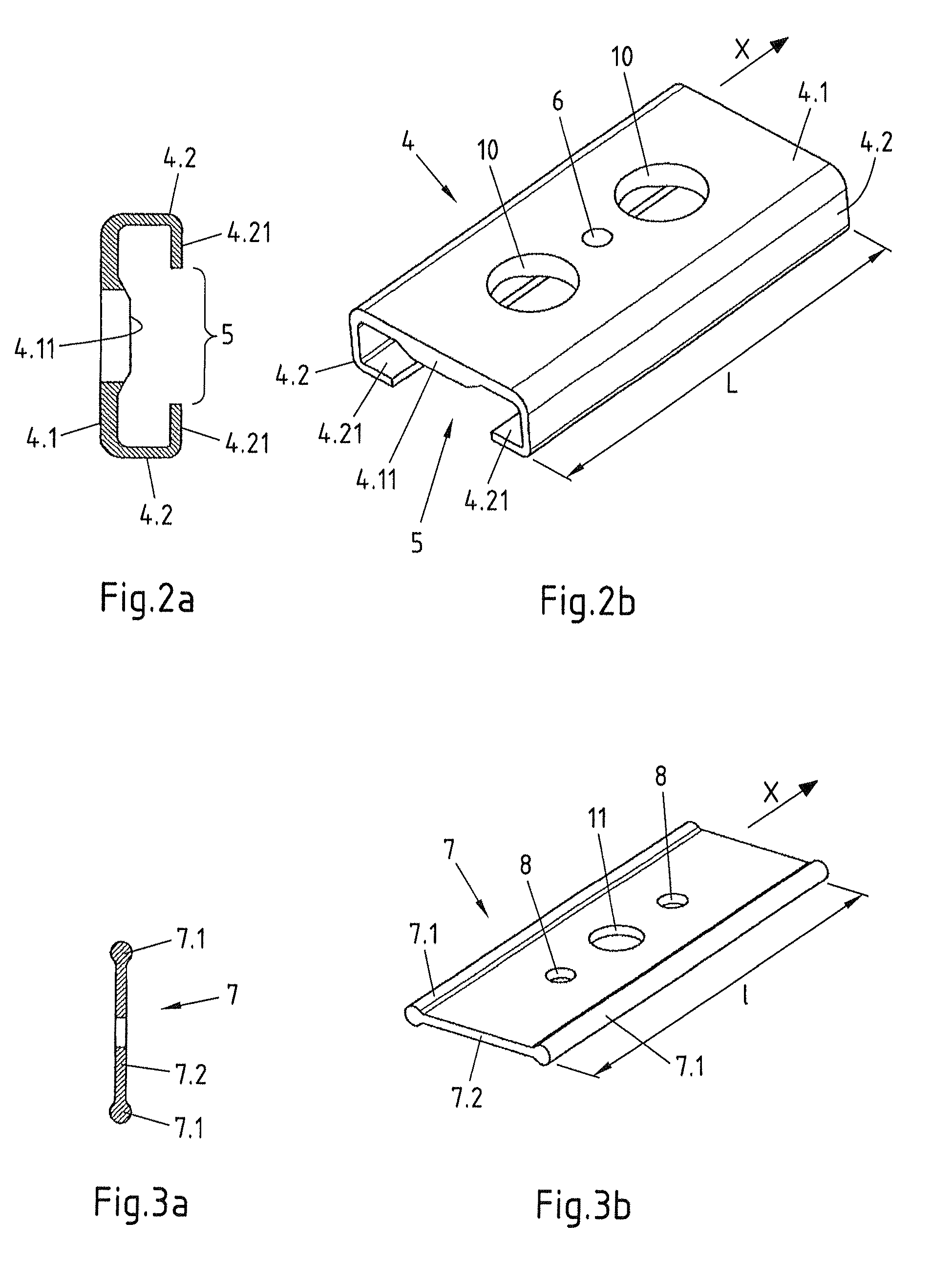 Figure 2a~3b
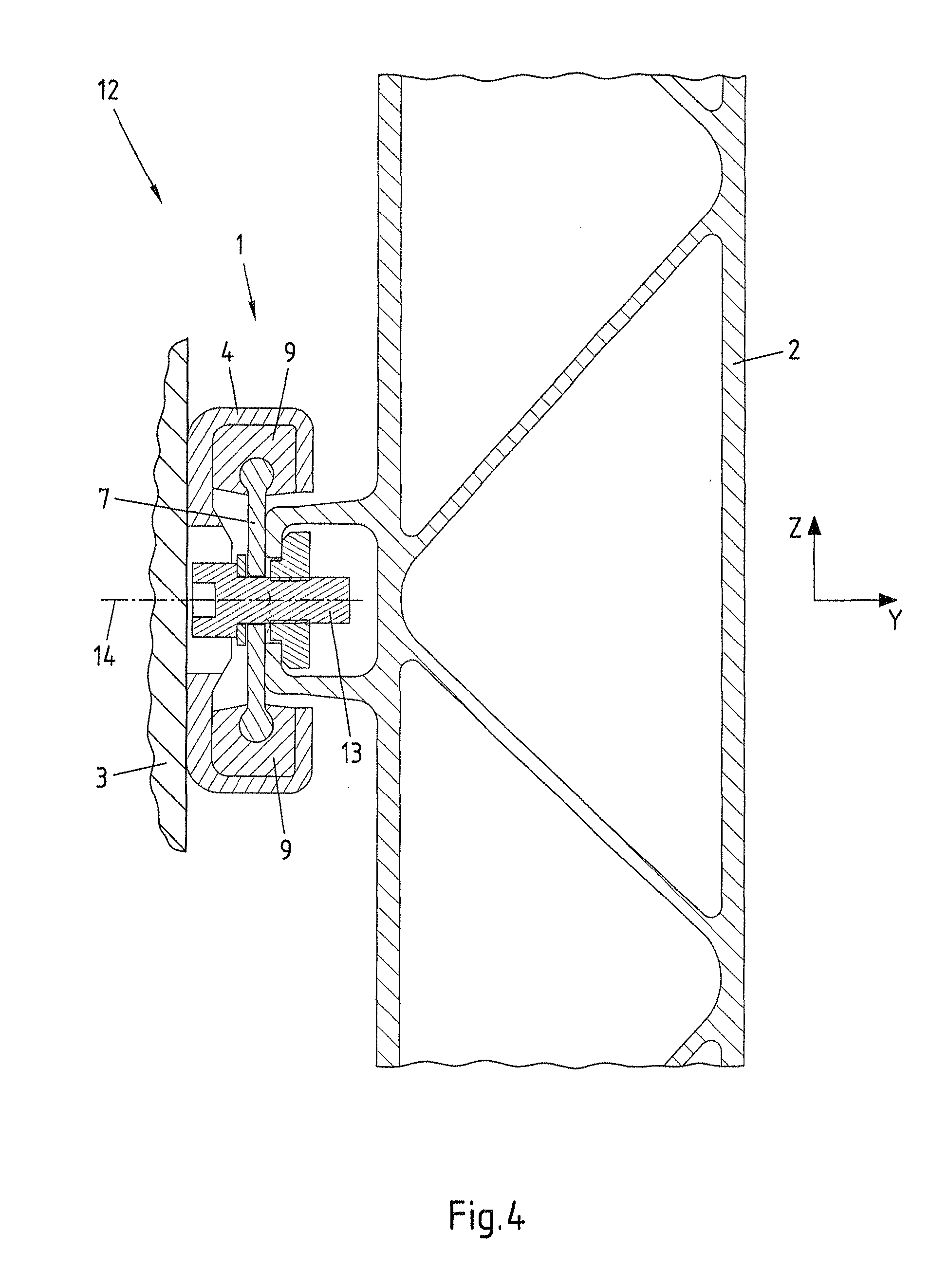 Figure 4
AI summary
The invention relates to a connecting element (1) for a vibration- and sound-damping connection between two components (2, 3), comprising a retaining rail (4) which extends in a longitudinal direction (X) and which has a base connecting piece (4.1) that extends in the longitudinal direction (X) and two lateral connecting pieces (4.2) that start from the base connecting piece (4.1), are mutually spaced, and extend in the longitudinal direction (X). A gap (5) which runs in the longitudinal direction (X) is formed between the two lateral connecting pieces (4.2) such that the retaining rail (4) has a C-shaped cross-section. The connecting element also comprises a plate-shaped element (7) which is retained within the retaining rail (4) and which has at least one bore (8). The at least one bore (8) in the plate-shaped element (7) lies within the outer boundary of the retaining rail (4) with respect to the longitudinal direction (X). The connecting element also comprises a rubber-elastic damping material (9) which is arranged between the retaining rail (4) and the plate-shaped element (7) at least in some sections and in which at least two edges (7.1) of the plate-shaped element (7) are embedded such that the plate-shaped element (7) does not contact the retaining rail. The invention further relates to a connecting arrangement (12) comprising such a connecting element (1) and to a rail vehicle comprising at least one such connecting arrangement (12).