
CO2 Liquefaction Stages Using Flue Gas Self-Cooling
Find Innovative SolutionsGenerate Solutions
Solution Overview
Problem
Existing carbon capture and sequestration (CCS) systems have high capital costs and environmental impacts due to the use of external refrigeration systems and refrigerants with high global warming potential, and they often require complex retrofits to meet the objectives of flexible carbon capture and storage (FLECCS) in power plants.
Innovation Solution
A CCS system that uses flue gas as the refrigerant, employing a modular design with a series of cooling and expansion stages to liquefy and separate CO2, utilizing heat exchangers and expanders to extract solid CO2, thereby reducing capital costs and environmental footprint.
Engineering Contradictions & Design Principles
Engineering Contradiction Analysis
1Reliability
If conventional amine carbon capture technology is used, then CO2 separation is achieved through reversible reactions, but capital costs increase to 4 or more times that of cryogenic systems
Solution Approach 1:
The patent extracts and removes the CO2 component from the flue gas stream through cryogenic cooling and phase separation, isolating it as a distinct liquid or solid phase that can be easily separated from the remaining gas stream, thereby achieving high separation efficiency without requiring expensive amine chemicals
Solution Approach 2:
The patent changes the temperature parameter of the flue gas from ambient conditions to cryogenic temperatures (below -78.5°C), causing CO2 to undergo phase changes from gas to solid dry ice or liquid, which enables separation based on phase differences rather than chemical reactions, significantly reducing capital costs
2Productivity
If externally cooled cryogenic carbon capture is used, then heat exchange efficiency is improved with smaller temperature differences, but capital cost increases due to bigger heat exchangers
Solution Approach 1:
The patent employs a self-cooling mechanism where the flue gas itself is cooled by expanding through a valve or turbine, causing adiabatic cooling and temperature drop without requiring external refrigeration systems or large heat exchangers, thereby achieving efficient cooling at lower capital cost
Solution Approach 2:
The patent replaces the mechanical external refrigeration system with a thermodynamic expansion process, where the gas undergoes adiabatic expansion through a valve or turbine to achieve cooling, substituting complex mechanical refrigeration equipment with a simpler thermodynamic process
3Reliability
If externally cooled cryogenic carbon capture is used, then CO2 capture is achieved, but system complexity increases due to specialized refrigerants and multiple heat pump subsystems
Solution Approach 1:
The patent makes the flue gas serve multiple functions: it is the process stream being treated, the cooling medium through adiabatic expansion, and the source of the separated CO2 product, eliminating the need for separate refrigeration systems and specialized refrigerants, thereby reducing system complexity while maintaining capture capability
Solution Approach 2:
The patent extracts the CO2 from the flue gas stream through cryogenic separation and removes the need for external refrigeration subsystems by using the flue gas itself for cooling through expansion, simplifying the overall system architecture
4Temperature
If R-14 refrigerant is used in externally cooled cryogenic systems, then cooling is achieved, but environmental impact increases due to high global warming potential
Solution Approach 1:
The patent converts the harmful high-GWP refrigerant into a beneficial role by using the flue gas itself as the cooling medium through adiabatic expansion, turning a source of CO2 emissions into a useful cooling resource, thereby eliminating the need for harmful refrigerants like R-14
Solution Approach 2:
The flue gas serves its own cooling function through adiabatic expansion, eliminating the need for external refrigeration systems that would require harmful refrigerants, making the system environmentally friendly while achieving the required cooling
Applied Scientific Principles
This section explains which scientific principles are used to turn an abstract innovation direction into a practical engineering solution.
Function Achieved in This Case
The system achieves high capture efficiency with low capital costs, minimizing the use of external refrigerants and avoiding complex refrigeration systems, resulting in a cost-effective and environmentally friendly CO2 capture process.
Implementation Method 1
a first cooling stage to cool flue gas with liquid CO2
Implementation Method 2
a compression stage coupled to the first cooling stage to compress the cooled flue gas
Implementation Method 3
a second cooling stage coupled to the compression stage and the first cooling stage to cool the compressed flue gas with a CO2 melt
Implementation Method 4
an expansion stage coupled to the second cooling stage to extract solid CO2 from the flue gas that melts in the second cooling stage
Implementation Method 5
extract solid CO2 from the flue gas that melts in the second cooling stage to provide the liquid CO2
Data Source
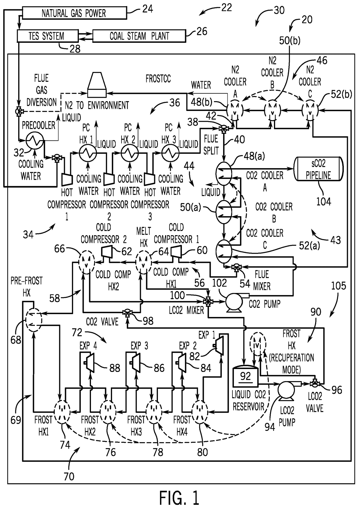 Figure 1
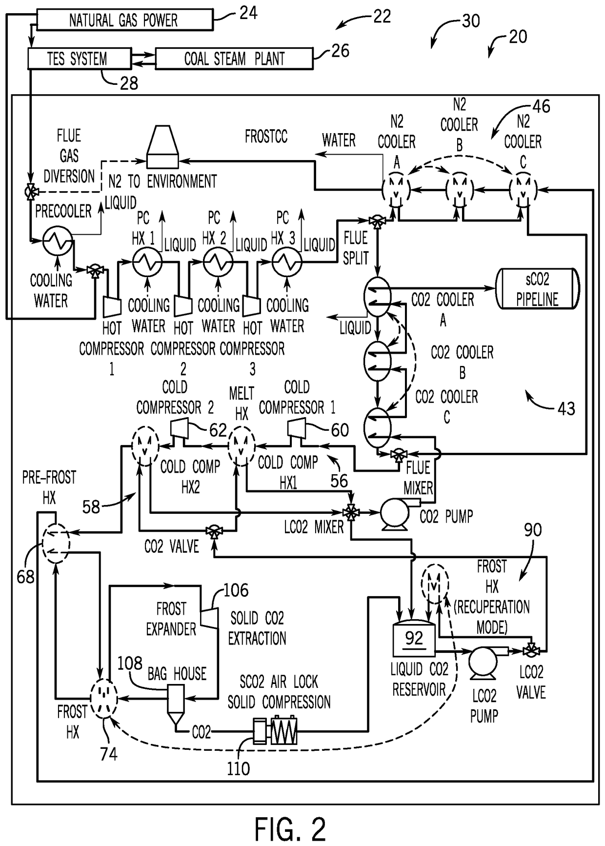 Figure 2
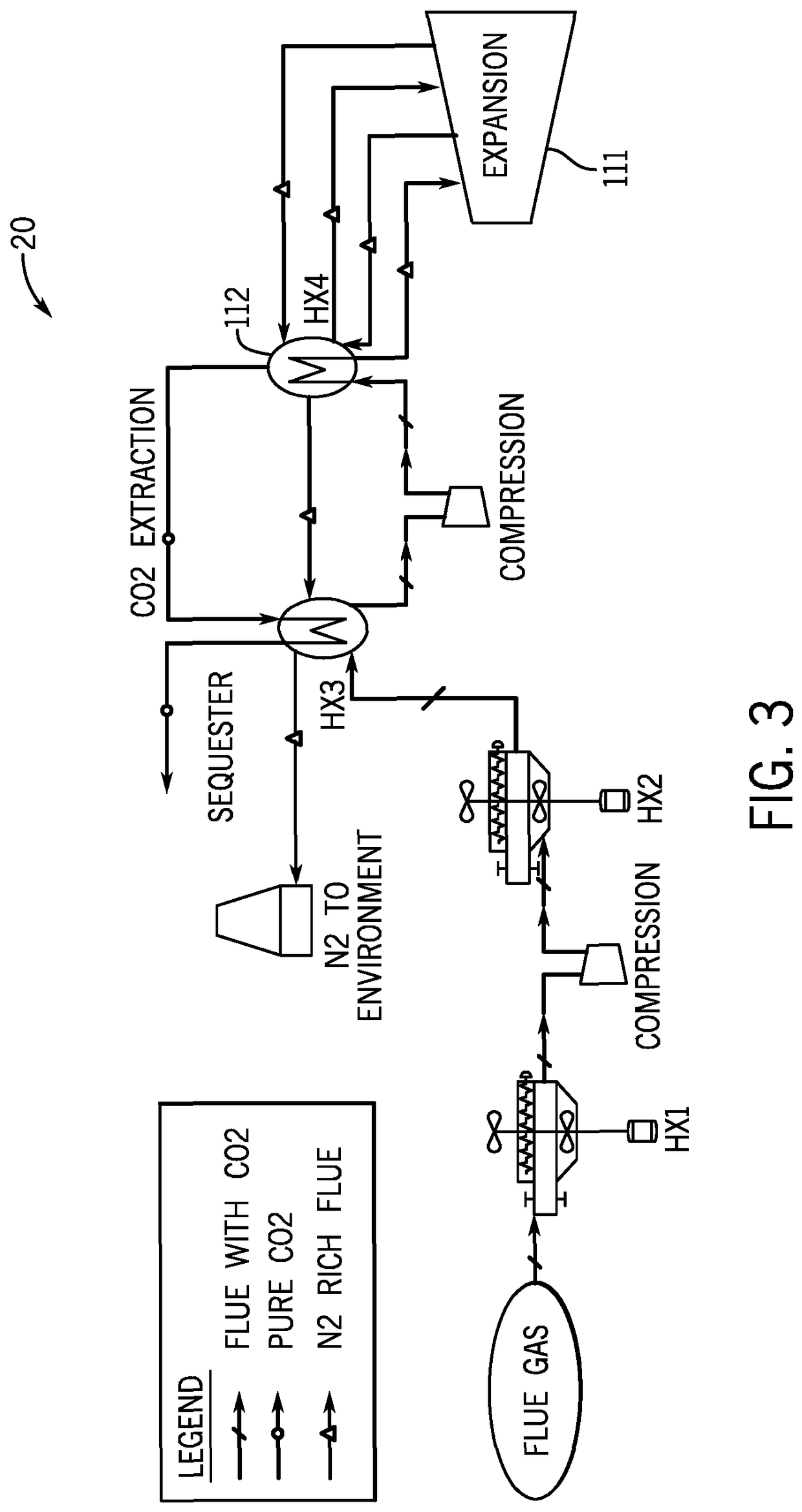 Figure 3
AI summary
A CO2 separation and liquefaction system such as might be used in a carbon capture and sequestration system for a fossil fuel burning power plant is disclosed. The CO2 separation and liquefaction system includes a first cooling stage to cool flue gas with liquid CO2, a compression stage coupled to the first cooling stage to compress the cooled flue gas, a second cooling stage coupled to the compression stage and the first cooling stage to cool the compressed flue gas with a CO2 melt and provide the liquid CO2 to the first cooling stage, and an expansion stage coupled to the second cooling stage to extract solid CO2 from the flue gas that melts in the second cooling stage to provide the liquid CO2.