

Door Lock Pulse Control Under DC Voltage Drop
Find Innovative SolutionsGenerate Solutions
Solution Overview
Problem
The use of a DC voltage source for locking devices in household appliances, such as washing machines, can lead to unreliable operation due to voltage drops when energy is delivered to other consumers, potentially preventing the locking element from being securely locked or held in the locking position, especially when using capacitors as DC voltage sources.
Innovation Solution
A locking device that adjusts the pulse length of control pulses to the drive element based on the current voltage value from the DC voltage source, ensuring a constant electrical power delivery to the drive element, thereby maintaining reliable operation without the need for galvanic isolation between control devices.
Engineering Contradictions & Design Principles
Engineering Contradiction Analysis
1Reliability
If a DC voltage source is used to supply the locking device, then galvanic isolation between control devices is achieved, but voltage drops occur when energy is delivered to other consumers
Solution Approach 1:
The control device continuously monitors the actual voltage at the DC voltage source and uses this feedback information to dynamically adjust the pulse length of control pulses. This closed-loop control ensures that sufficient energy is delivered to the locking device even when voltage drops occur due to other consumers drawing power from the same DC source.
Solution Approach 2:
The system transitions from using fixed, predetermined pulse lengths to dynamically adjustable pulse lengths that adapt in real-time to changing voltage conditions. This dynamic adjustment allows the locking device to maintain reliable operation across varying voltage levels caused by other consumers drawing power from the DC source.
2Device complexity
If fixed pulse length control is used, then control is simplified, but sufficient energy cannot be guaranteed when voltage drops occur
Solution Approach 1:
The control device continuously monitors the actual voltage at the DC voltage source and uses this feedback information to dynamically adjust the pulse length of control pulses. This closed-loop control ensures that sufficient energy is delivered to the locking device even when voltage drops occur due to other consumers drawing power from the same DC source.
Solution Approach 2:
The system changes the operational parameter of pulse length from a fixed value to a dynamically adjusted value based on actual voltage conditions. By modifying the pulse length parameter in response to voltage drops, the system ensures sufficient energy delivery while maintaining a relatively simple overall control structure.
3Area of stationary object
If multiple consumers are supplied from the same DC voltage source, then device integration is improved, but voltage collapse occurs when energy is delivered
Solution Approach 1:
The control device continuously monitors the actual voltage at the DC voltage source and uses this feedback information to dynamically adjust the pulse length of control pulses. This closed-loop control ensures that sufficient energy is delivered to the locking device even when voltage drops occur due to other consumers drawing power from the same DC source.
Solution Approach 2:
The system transitions from using fixed, predetermined pulse lengths to dynamically adjustable pulse lengths that adapt in real-time to changing voltage conditions. This dynamic adjustment allows the locking device to maintain reliable operation across varying voltage levels caused by other consumers drawing power from the DC source.
Applied Scientific Principles
This section explains which scientific principles are used to turn an abstract innovation direction into a practical engineering solution.
Function Achieved in This Case
This approach ensures that the locking element is reliably brought into and held in the locking position, providing safe and consistent operation using a direct voltage source, eliminating the need for additional isolation measures and maintaining reliable operation across varying voltage conditions.
Implementation Method 1
An electromagnet in the form of an electrical coil is usually used, which acts as a drive element for the actual locking bolt
Data Source
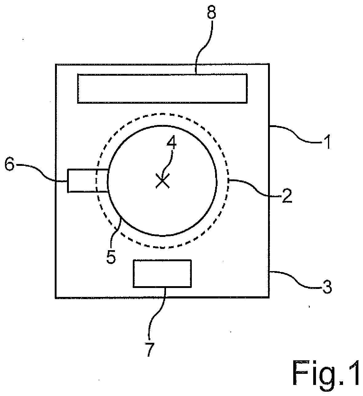 Figure 1
 Figure 2
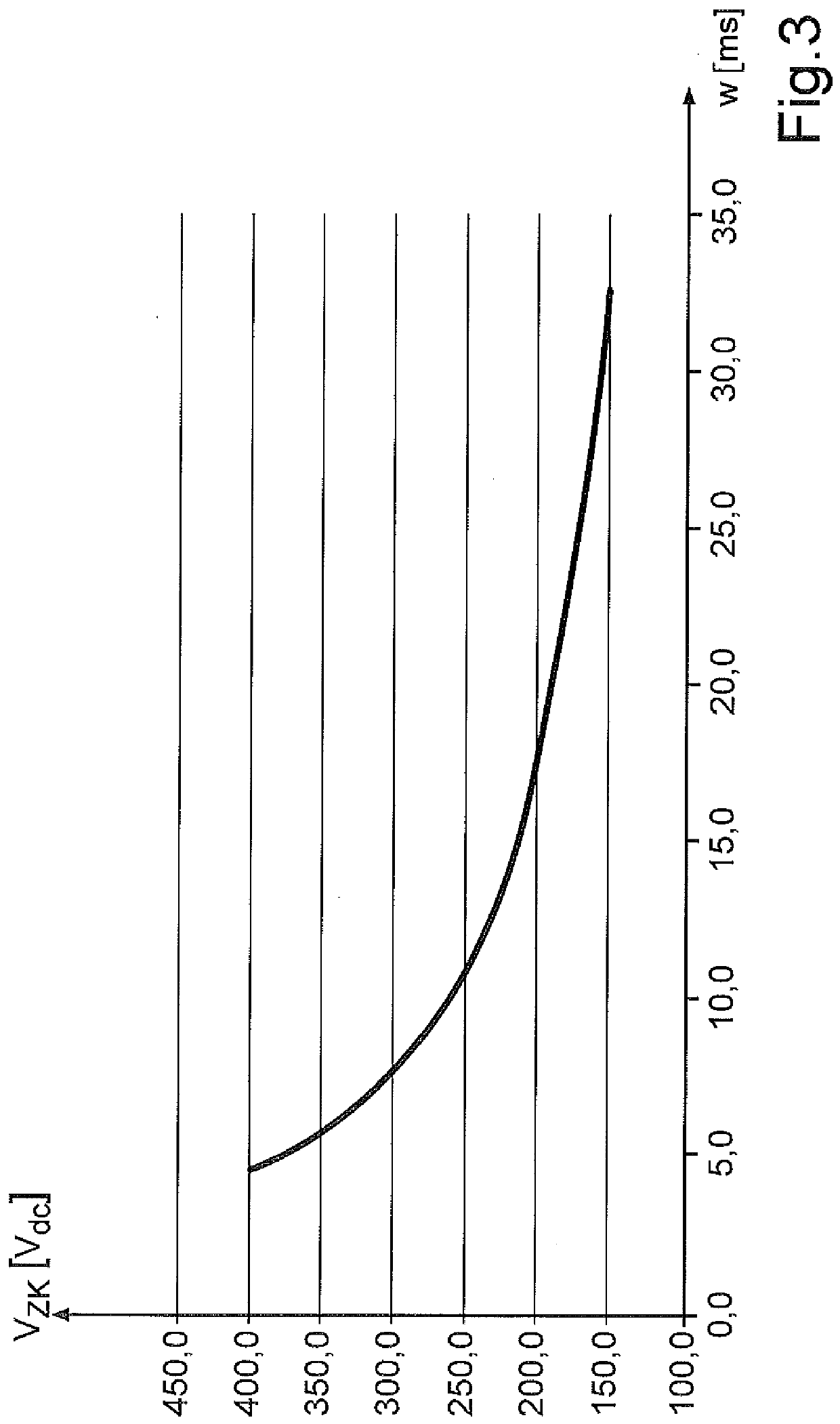 Figure 3
AI summary
The invention relates to a locking device (6) for locking a door (5) of a domestic appliance (1), comprising a locking element (27) for mechanically locking the door (5), comprising a driving element (20) for moving the locking element (27) from an unlocking position in which the door (5) is unlocked into a locking position in which the door (5) is locked by the locking element (27), depending upon a current flow (I) through the driving element (20), wherein the driving element (20) is electrically coupled to a DC voltage source (12), comprising a switching element (22, 23) electrically coupled to the driving element (20) for controlling the current flow (I) through the driving element (20), and comprising a control unit (25) for controlling the switching element (22, 23), wherein the control unit (25) is designed for controlling the current flow (I) through the driving element (20) to emit a sequence of control pulses (30) to the switching element (22, 23). The locking device (6) comprises means for detecting a current voltage value (V) of a DC voltage (VZK) provided by the DC voltage source (12), wherein the control unit (25) is designed to adjust a pulse length (w) of the control pulses (30) as a function of the current voltage value (V).