
Expansion Seal Joint Profile With Hook Retaining Elements
Find Innovative SolutionsGenerate Solutions
Solution Overview
Problem
Existing joint profiles for movement joints between building parts suffer from increased wear when the building parts are not at the same height, leading to a step formation in the usable area, especially under heavy goods traffic, due to the design of the known joint profiles which results in mechanical stress and material inefficiency.
Innovation Solution
The joint profile incorporates hook-shaped retaining elements and undercut grooves for a form-fitting connection between joint heads and sockets, a center plate mounted in a groove for displacement compensation, and a conically tapering cover area to avoid steps and reduce material requirements, allowing for efficient load distribution and reduced internal stresses.
Engineering Contradictions & Design Principles
Engineering Contradiction Analysis
1Strength
If the joint profile is designed with a symmetrical structure and straight teeth for heavy loads, then the load-bearing capacity is improved, but a step forms in the usable area when building parts are at different heights, leading to increased wear
Solution Approach 1:
The patent applies asymmetry by designing the joint socket to enclose the joint head in a circular arc of less than 180°, creating an asymmetric configuration that eliminates steps in the usable area when building parts are at different heights, thereby reducing wear while maintaining load-bearing capacity through the articulated connection
2Reliability
If the joint socket encloses the joint head in a larger arc, then the form-fitting connection and load distribution are improved, but the material requirements and device complexity increase
Solution Approach 1:
The patent applies partial action by designing the joint socket to enclose the joint head in a circular arc of less than 180° (partial enclosure), which is sufficient to provide the necessary form-fitting connection and load distribution while reducing material requirements and simplifying the device structure compared to full 360° enclosure
Data Source
 Figure 1
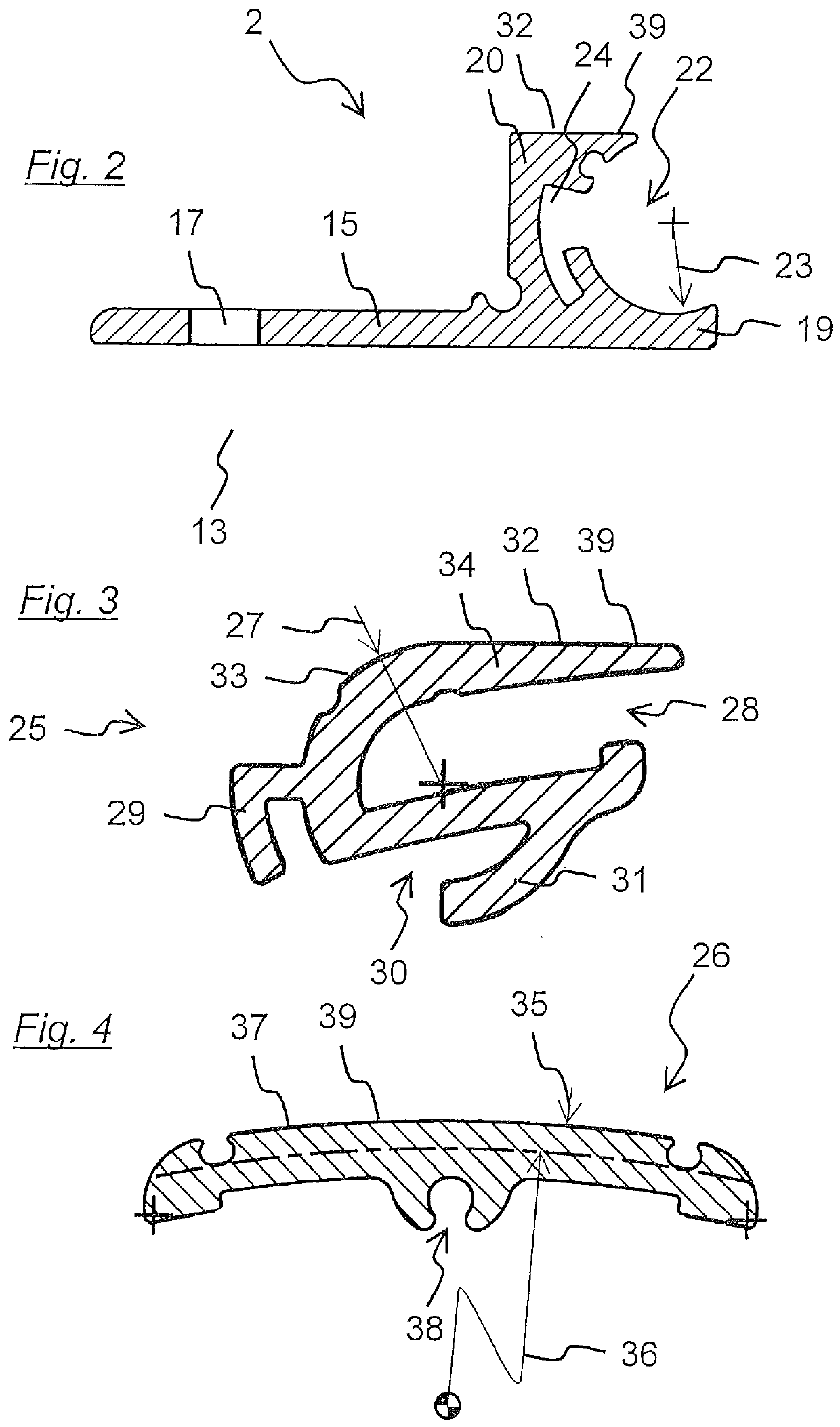 Figure 2~4
AI summary
Joint profile (1) for an expansion joint (4) in a surface (6) of a structure between two parallel structural elements (7) of the structure, comprising two anchor units (2) for anchoring the joint profile (1) to the structural elements (7), each anchor unit (2) having a circular arc-shaped groove extending in a longitudinal direction (14) of the expansion joint (4), and a bridge unit (3) for bridging the expansion joint (4) between the anchor units (2), which has two circular arc-shaped profiled joint heads (25) extending in the longitudinal direction (14), with which the bridge unit (3) pivotally rests in the joint sockets, the bridge unit (3) pivotally resting with the joint heads (25) in the joint sockets such that a load acting perpendicular to the surface (6) on the bridge unit (3) is transferred via the joint heads (25) to the joint sockets and from the Anchor units (2) are directed onto the structural components (7),and wherein a positive-locking connection prevents displacement of the joint heads (25) relative to the respective joint socket transversely to the longitudinal direction (14). To improve the joint profile (1), it is proposed that the positive-locking connection be formed by hook-shaped retaining elements extending in the longitudinal direction (14) on the joint heads (25), and by hook-shaped undercut grooves in the joint sockets into which the retaining elements engage.