

Rolling Electrical Contact Assembly for Stable High-Current Transfer
Find Innovative SolutionsGenerate Solutions
Solution Overview
Problem
Existing rotary electrical conductors face issues such as contact resistance growth, temperature increase, oxidation, and wear due to poor alignment and friction, especially in marine environments, limiting their ability to efficiently transfer high electrical currents.
Innovation Solution
A rolling electrical contact assembly with a specific arrangement of ring-shaped angled conductive contact surfaces and roller-holder assemblies, featuring a pressing device to apply precise contact pressure, reducing wear and maintaining stable contact, allowing for efficient high-current transfer.
Engineering Contradictions & Design Principles
Engineering Contradiction Analysis
1Reliability
If sliding contacts with brushes and slip rings are used, then electrical current can be transferred to rotary parts, but contact resistance grows and temperature increases due to friction and wear
Solution Approach 1:
The patent replaces the traditional sliding contact mechanism with a rolling contact mechanism using rollers. This substitution transforms the friction-based sliding motion into rolling motion, dramatically reducing friction and wear between contact surfaces, thereby preventing temperature increase and maintaining stable electrical current transfer.
Solution Approach 2:
The patent changes the contact mode parameter from sliding to rolling. By modifying the fundamental nature of the contact interaction between stationary and rotating components, the system achieves lower friction coefficients and reduced contact resistance, solving the temperature and reliability contradiction.
2Reliability
If sliding contacts with brushes and slip rings are used, then electrical current can be transferred to rotary parts, but oxidation and wear occur on contact surfaces over time
Solution Approach 1:
The patent replaces the sliding contact mechanism with a rolling contact mechanism using rollers. This substitution dramatically reduces friction and wear between contact surfaces, preventing material degradation and oxidation that occur with traditional sliding contacts, thereby maintaining long-term reliability.
3Force
If coaxial rolling rings are used, then rolling contact reduces friction, but correct alignment is difficult to obtain during assembly
Solution Approach 1:
The patent introduces a stationary ring as an intermediary element that guides and supports the rollers. This stationary ring ensures correct alignment and concentricity between the stationary and rotating rings, making assembly easier while maintaining the friction-reducing rolling contact.
4Force
If cone-shaped bodies rolling on rings are used, then friction is reduced and contact is permanent, but manufacturing precision requirements are very high
Solution Approach 1:
The patent introduces a stationary ring as an intermediary that guides the rollers, ensuring proper alignment and line contact formation. This intermediary element reduces the manufacturing precision requirements for the cone-shaped bodies while maintaining permanent rolling contact and friction reduction.
5Power
If multiple layers of rolling rings are used to transfer multiple power transmissions, then more power can be transferred, but the overall space requirement increases
Solution Approach 1:
The patent arranges multiple power transmission paths in a nested configuration around a common stationary ring. This allows multiple rolling contacts to share the same central space, enabling high power transmission capacity without proportionally increasing the overall volume of the conductor assembly.
Applied Scientific Principles
This section explains which scientific principles are used to turn an abstract innovation direction into a practical engineering solution.
Function Achieved in This Case
The solution enables stable and efficient transfer of high electrical currents with reduced wear and contact resistance, facilitating easier assembly and maintenance, and is suitable for applications like ship pods and wind turbines.
Implementation Method 1
at least one pressing device exerting a force F on said roller or pair of rollers along said shaft
Implementation Method 2
one roller or a pair of rollers each comprising a ring-shaped angled electrically conductive contact surface conformed to roll onto the corresponding contact surfaces of the first and second electrodes
Data Source
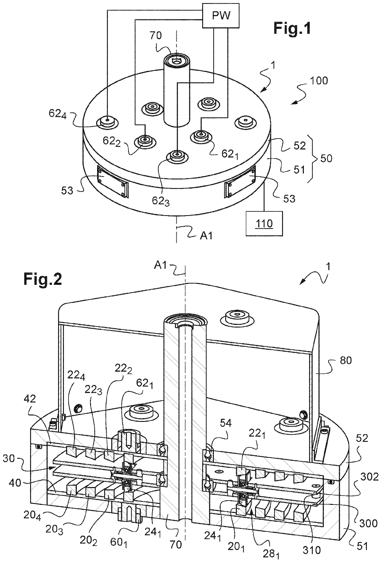 Figure 1~2
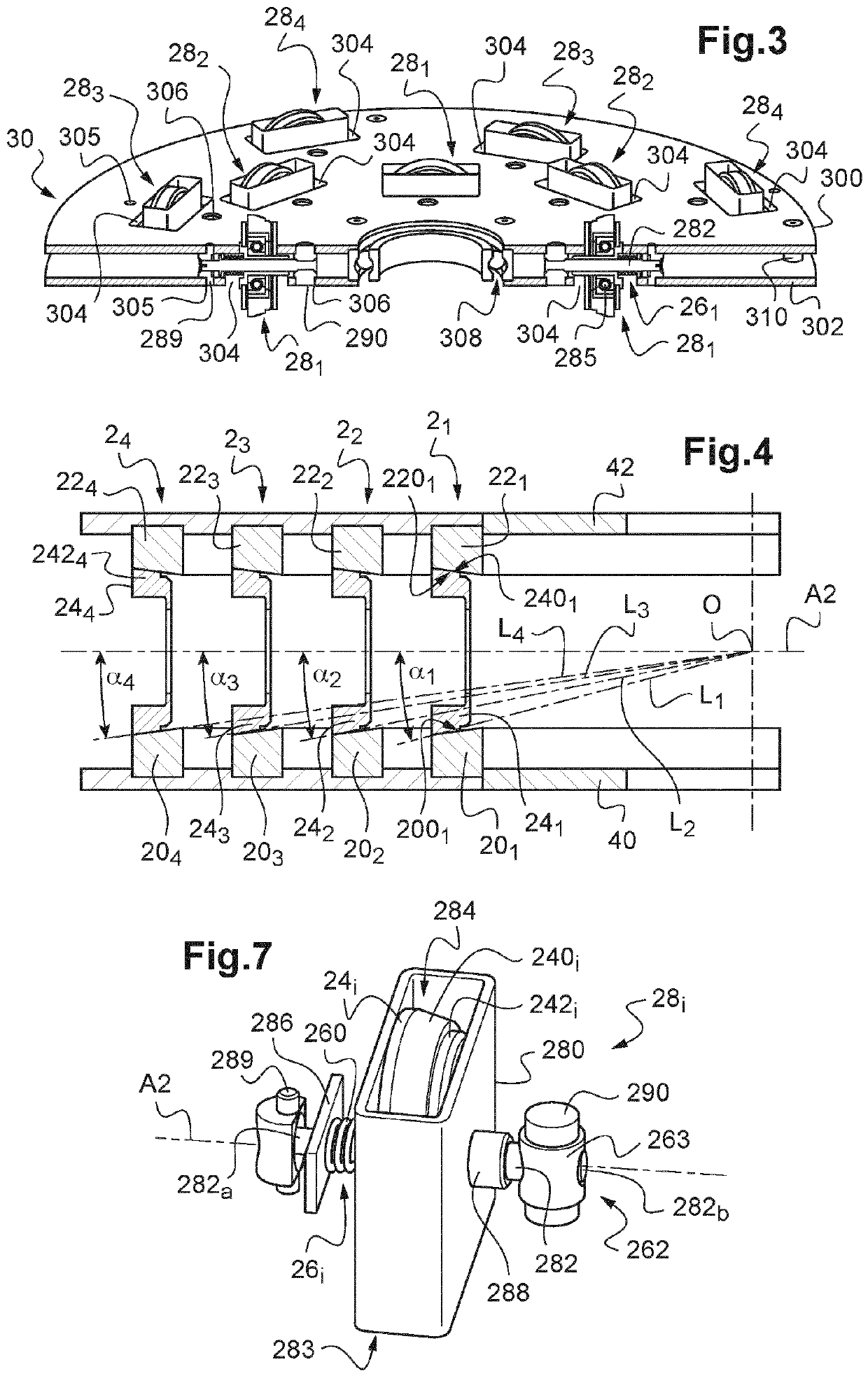 Figure 3~7
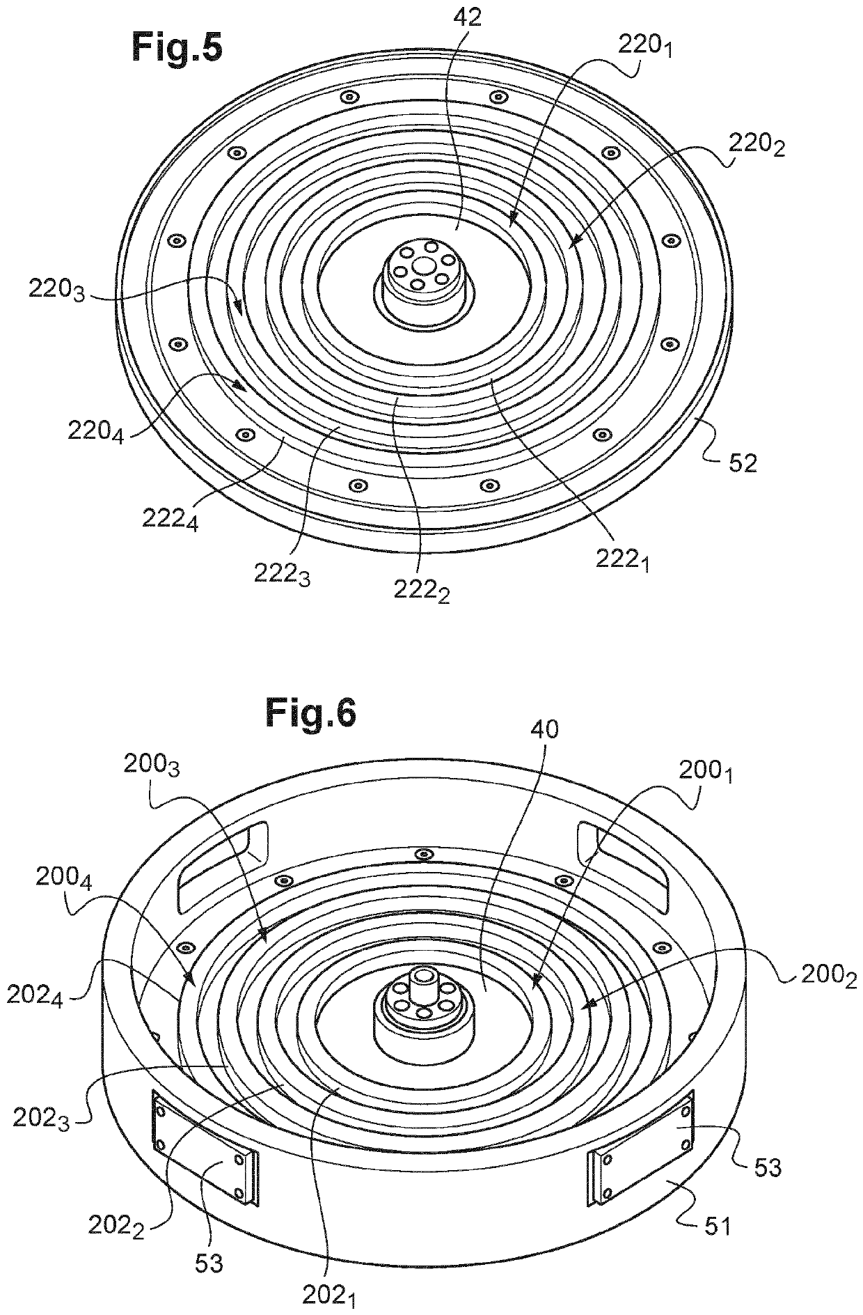 Figure 5~6
AI summary
The invention concerns a rolling electrical contact assembly (1) for transferring current between two relatively rotatable parts, comprising at least one power transmission set including: - a first electrode (201, 202, 203, 204,) and a second electrode (221, 222, 223, 224,), comprising each a ring-shaped angled electrically conductive contact surface of same first axis (A1), - at least one roller-holder assembly (281) comprising one roller (241), or a pair of rollers, each comprising: - a ring-shaped angled electrically conductive contact surface conformed to roll onto the corresponding contact surfaces of the first and second electrodes while the first electrode is rotating, - a shaft defining a second axis (A2) around which is rotatably is mounted each roller (241), - at least one pressing device exerting a force F on each roller along said shaft. The rolling electrical contact assembly (1) further comprises two supporting members (300, 302) rotatably mounted around the first axis and assembled to each other spaced along said first axis by a distance inferior to a minimal diameter of the contact surfaces of each roller, between which are mounted each roller-holder assembly (281) in a position wherein the second axis (A2) is radial to the first axis (A1), the contact surface of each roller protrudes from apertures provided in the supporting members and the pressing device exerts a force F in the direction of the first axis.