

Hybrid Torque Bar Assembly With Additive-Built Wear Surfaces
Find Innovative SolutionsGenerate Solutions
Solution Overview
Problem
Conventional torque bars for aircraft brake systems face limitations in geometry and material waste due to traditional manufacturing techniques, which affect their ability to resist deflection and wear, and are heavy and costly.
Innovation Solution
A hybrid torque bar design using additive manufacturing techniques for specific components, combining a base portion formed through traditional methods with pins and rails optimized for wear resistance and thermal properties, featuring a gradient transition of wear-resistant coatings for enhanced performance.
Engineering Contradictions & Design Principles
Engineering Contradiction Analysis
1Shape
If conventional subtractive manufacturing techniques are used to make torque bars, then the manufacturing process is simple and well-established, but the geometry is limited and material waste is high
Solution Approach 1:
The patent transitions from conventional subtractive manufacturing to additive manufacturing, fundamentally changing the manufacturing parameter approach. This enables complex geometries (including internal channels and lattice structures) that cannot be achieved through traditional machining, while simultaneously reducing material waste by building parts only where material is needed.
Solution Approach 2:
The patent employs multi-material additive manufacturing to create composite torque bars with different metal alloys in different regions. This allows optimization of specific areas for particular functions (e.g., wear resistance at contact points, thermal conductivity in brake proximity) while maintaining overall structural integrity and reducing total material usage.
2Reliability
If conventional subtractive manufacturing techniques are used to make torque bars, then the manufacturing process is straightforward, but wear resistance and deflection resistance are limited
Solution Approach 1:
The patent applies local quality by using multi-material additive manufacturing to create regions with different properties within the same torque bar. High-wear areas receive wear-resistant metal alloys, while other regions use materials optimized for strength or thermal properties. This localized optimization enhances overall reliability without requiring the entire part to be made from excessive material.
Solution Approach 2:
The torque bar is constructed as a composite structure with multiple metal alloys deposited in specific regions. This allows the integration of wear-resistant materials at critical contact surfaces while maintaining structural integrity throughout the component, achieving superior wear resistance without uniform over-engineering.
3Adaptability or versatility
If a single metal alloy is used throughout the torque bar, then the manufacturing process is simpler, but the ability to optimize for different functions (wear resistance, thermal stability, strength) is reduced
Solution Approach 1:
The patent implements local quality by assigning different metal alloys to different regions of the torque bar based on functional requirements. Areas subject to wear use wear-resistant alloys, regions near brake components use thermally conductive alloys, and structural areas use high-strength alloys. This spatial differentiation of material properties enables multi-functional optimization within a single component.
Solution Approach 2:
The torque bar is designed as a multi-material composite structure where different metal alloys are integrated at the material level. This allows simultaneous optimization for wear resistance, thermal management, and structural strength within a single monolithic component, achieving versatility without requiring multiple separate parts.
Data Source
 Figure 1
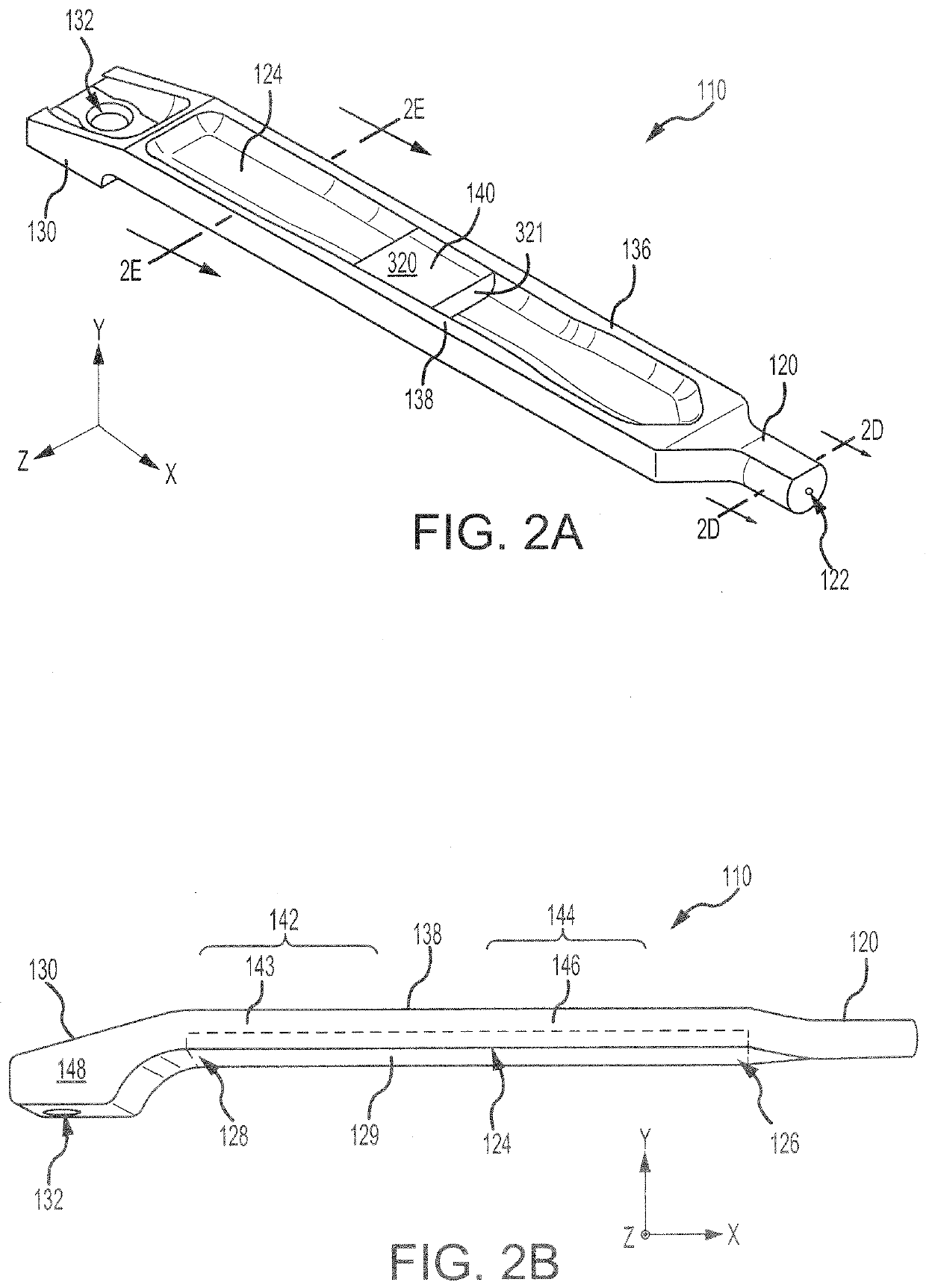 Figure 2A~2B
 Figure 2C~2E
AI summary
A hybrid torque bar (110) for a brake assembly may comprise a base portion (124), a pin (120) extending from a first end of the base portion (124), and a rail (136) extending between the first end of the base portion (124) and a second end of the base portion (124) opposite the first end. The base portion (124) may be formed using a first manufacturing process. At least one of the pin (120) or the rail (136) may formed using a second manufacturing process. The second manufacturing process may comprise an additive manufacturing technique.