

Type-2 Compensation Circuit for Low Quiescent Current Stability
Find Innovative SolutionsGenerate Solutions
Solution Overview
Problem
Type-2 compensation circuits in switch-mode power supplies face challenges in reducing quiescent current without affecting unity gain bandwidth, which is crucial for maintaining stability and efficiency, especially in light load situations where traditional methods alter system dynamics and stability.
Innovation Solution
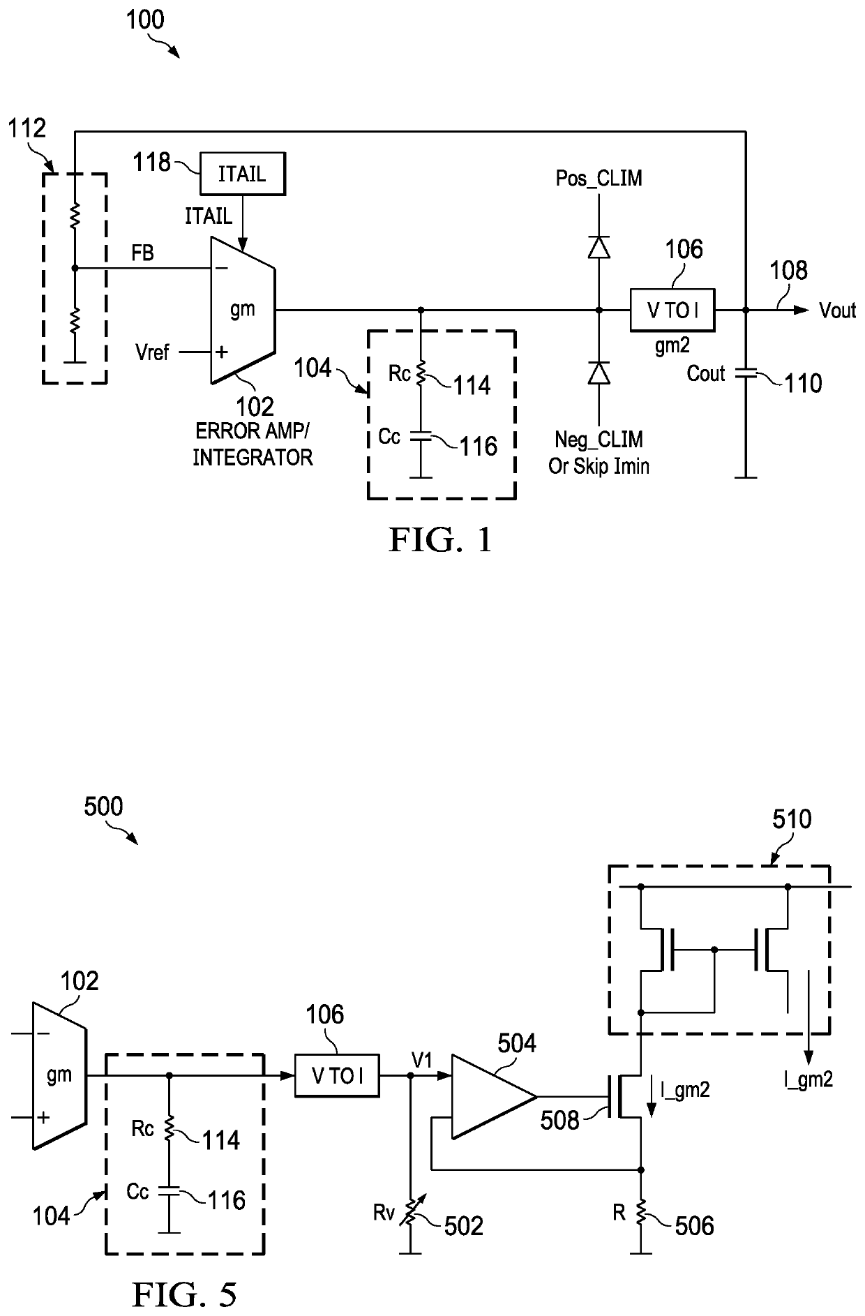
The implementation of a compensation circuit that includes a tail current source, an error amplifier, a variable compensation resistor, and a voltage-to-current converter, where the resistance or transconductance of the compensation components adjusts in response to changes in tail current to maintain unity gain bandwidth, allowing for reduced quiescent current consumption without compromising circuit stability.
Engineering Contradictions & Design Principles
Engineering Contradiction Analysis
1Use of energy by stationary object
If traditional compensation circuits are used to reduce quiescent current, then power consumption decreases, but unity gain bandwidth changes affecting stability
Solution Approach 1:
The compensation circuit dynamically adjusts the compensation resistance based on the tail current of the error amplifier. As the tail current changes with load conditions, the compensation resistance automatically adapts to maintain a constant unity gain bandwidth, ensuring stability across all operating conditions while allowing quiescent current reduction at light loads.
Solution Approach 2:
The circuit changes the compensation resistance parameter in response to tail current variations. By monitoring the tail current and adjusting the compensation resistance accordingly, the system maintains the product of compensation resistance and error amplifier transconductance constant, thereby preserving unity gain bandwidth while enabling quiescent current reduction.
2Productivity
If quiescent current is reduced in light load situations, then power efficiency improves, but system dynamics and stability are altered
Solution Approach 1:
The compensation circuit is designed to be dynamic, automatically adjusting compensation resistance based on real-time tail current measurements. This dynamic adaptation allows the system to operate efficiently at light loads with reduced quiescent current while maintaining proper stability characteristics when load conditions change.
Solution Approach 2:
The circuit implements feedback by monitoring the tail current of the error amplifier and using this information to adjust the compensation resistance. This feedback mechanism ensures that the unity gain bandwidth remains constant despite variations in quiescent current, thereby maintaining system dynamics and stability while improving power efficiency.
Data Source
AI summary
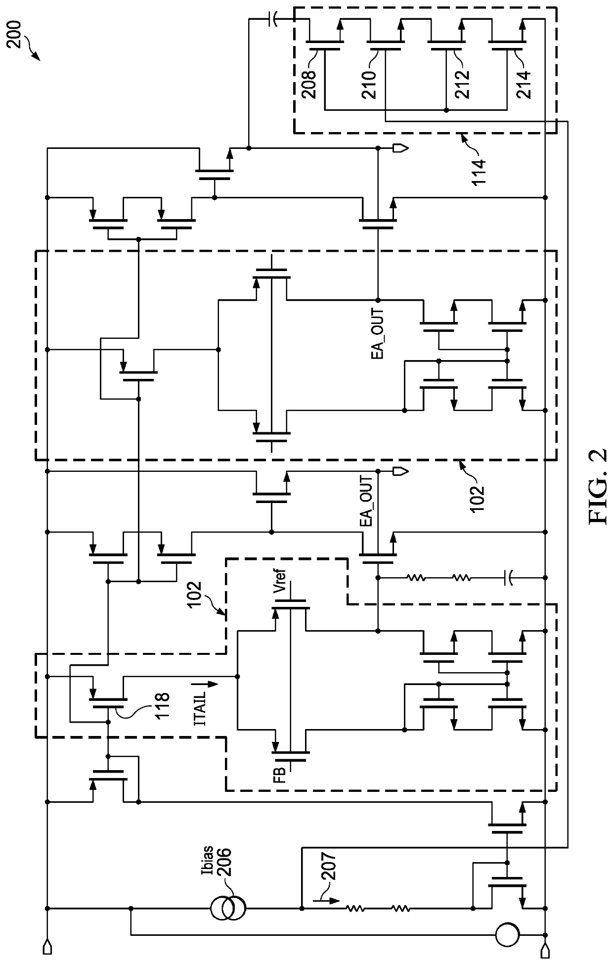
A compensation circuit includes a tail current source, an error amplifier; a compensation resistor, and a voltage-to-current converter circuit. The tail current source is configured to generate a tail current. The error amplifier is coupled to the tail current source and biased by the tail current. The compensation resistor is coupled to the error amplifier. The voltage-to-current converter circuit is coupled to the error amplifier. The compensation resistor is configured to vary in resistance responsive to a change in the tail current, or the voltage-to-current converter circuit is configured to vary in transconductance responsive to the change in the tail current.