How to Create a Simple Power Supply Circuit Using Basic Design Methods?
JUN 27, 2025 |
Creating a power supply circuit can be an enriching project for electronics enthusiasts, providing a fundamental understanding of how electricity can be converted, regulated, and distributed. Before diving into the design process, it is crucial to grasp the basic components and functions of a power supply circuit. Generally, a power supply circuit converts AC (alternating current) from the mains to DC (direct current) suitable for electronic devices. This conversion involves several key components, including a transformer, rectifier, filter, and voltage regulator.
Choosing the Right Components
1. **Transformers**
The transformer is used to step down the voltage from the mains to a safer, lower level suitable for the circuit. It consists of primary and secondary windings. By selecting the right transformer, you can ensure that your circuit meets the voltage and current requirements for your specific application.
2. **Rectifier**
The rectifier converts AC to DC. It typically consists of diodes arranged in configurations such as a half-wave or full-wave rectifier. The full-wave rectifier is often preferred for its efficiency in converting AC to DC, using either a bridge configuration or a center-tapped transformer.
3. **Filters**
After rectification, the DC output contains ripples which need to be smoothed out. Capacitor filters are commonly used to reduce voltage fluctuations. Depending on the level of smoothness required, you might opt for additional filtering stages using inductors or other components.
4. **Voltage Regulators**
Voltage regulators ensure a constant output voltage regardless of variations in input voltage or load conditions. Linear voltage regulators are popular for their simplicity and can be used for low-power applications. Switching regulators, though more complex, offer higher efficiency, especially for applications demanding greater power.
Designing Your Power Supply Circuit
Start by determining the voltage and current requirements for your application, as these specifications will guide your component selection. For example, if your device requires 5V DC at 1A, you would select a transformer that outputs a secondary voltage suitable for stepping down to 5V after rectification and regulation.
1. **Schematic Planning**
Begin by sketching a schematic diagram of your proposed power supply circuit. This should include the transformer, rectifier, filter, and regulator. Mapping out the electrical connections helps visualize the design and identify potential issues.
2. **Component Assembly**
Once your schematic is ready, gather all necessary components and tools such as soldering equipment, a breadboard for prototyping, and measuring instruments. Begin assembling the circuit following your diagram, ensuring each component is securely connected and correctly oriented, particularly the diodes in the rectifier.
3. **Testing and Troubleshooting**
Before powering your circuit, double-check all connections and components to prevent any mishaps. Use a multimeter to ensure continuity and measure voltage at various points in the circuit. If the output is not as expected, consider troubleshooting common issues such as incorrect diode orientation, faulty components, or insufficient filtering.
Safety Considerations
When handling electrical components, especially those connected to mains power, safety should be your utmost priority. Always work in a dry, well-ventilated area and avoid touching live wires. Use insulated tools and wear protective gear if necessary. Understanding the limitations of your components can prevent overload and potential hazards.
Conclusion
Creating a simple power supply circuit is an excellent way to deepen your understanding of electronics and electrical engineering. With careful planning, appropriate component selection, and strict adherence to safety practices, you can successfully design a functional power supply circuit. The skills acquired through such projects lay the foundation for more complex endeavors in the field of electronics.
Accelerate Electronic Circuit Innovation with AI-Powered Insights from Patsnap Eureka
The world of electronic circuits is evolving faster than ever—from high-speed analog signal processing to digital modulation systems, PLLs, oscillators, and cutting-edge power management ICs. For R&D engineers, IP professionals, and strategic decision-makers in this space, staying ahead of the curve means navigating a massive and rapidly growing landscape of patents, technical literature, and competitor moves.
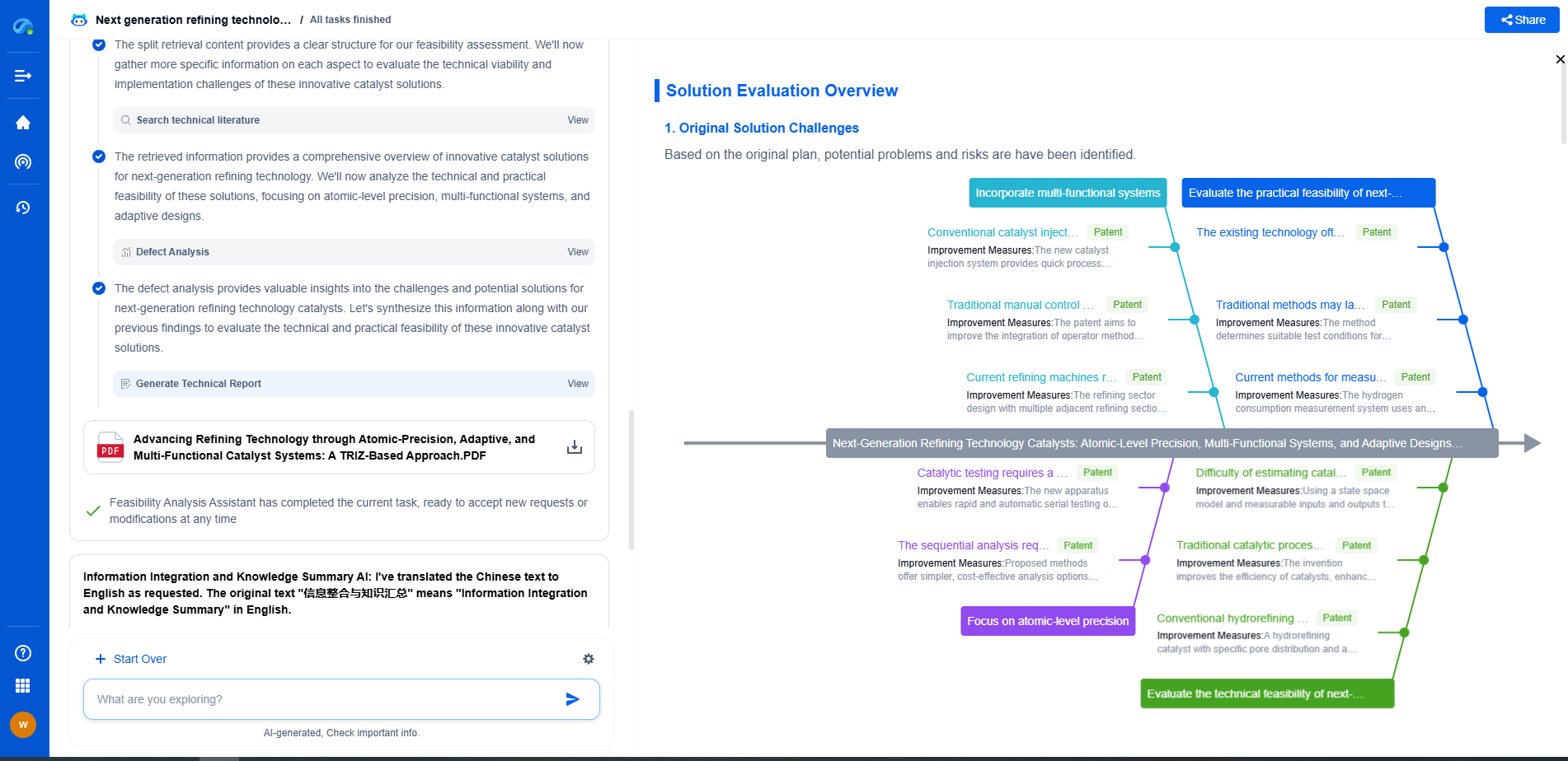
Patsnap Eureka, our intelligent AI assistant built for R&D professionals in high-tech sectors, empowers you with real-time expert-level analysis, technology roadmap exploration, and strategic mapping of core patents—all within a seamless, user-friendly interface.
🚀 Experience the next level of innovation intelligence. Try Patsnap Eureka today and discover how AI can power your breakthroughs in electronic circuit design and strategy. Book a free trial or schedule a personalized demo now.
- R&D
- Intellectual Property
- Life Sciences
- Materials
- Tech Scout
- Unparalleled Data Quality
- Higher Quality Content
- 60% Fewer Hallucinations
Browse by: Latest US Patents, China's latest patents, Technical Efficacy Thesaurus, Application Domain, Technology Topic, Popular Technical Reports.
© 2025 PatSnap. All rights reserved.Legal|Privacy policy|Modern Slavery Act Transparency Statement|Sitemap|About US| Contact US: help@patsnap.com

