How to Optimize Impedance Matching in RF Circuits? Tools and Techniques
JUN 26, 2025 |
Understanding the Importance of Impedance Matching
Impedance matching is essential in RF circuits to ensure that the maximum amount of power is transferred from the source to the load. When the impedance of the source and the load are matched, signal reflections are minimized, resulting in improved signal integrity and reduced losses. Impedance mismatches can lead to power loss, increased distortion, and reduced bandwidth, making it crucial to address them in RF design.
Common Impedance Matching Techniques
1. **Lumped Element Matching**
Lumped element matching involves using discrete components, such as inductors and capacitors, to match impedances. This technique is popular in RF design due to its simplicity and effectiveness. The two main types of lumped element matching networks are L-networks and Pi-networks. L-networks are suitable for matching a high impedance to a low impedance or vice versa, while Pi-networks offer more flexibility and can provide additional filtering.
2. **Transmission Line Matching**
Transmission line matching uses the properties of transmission lines to achieve impedance matching. This technique is particularly useful at higher frequencies where lumped elements become impractical. Transmission line matching can be accomplished using quarter-wave transformers or stub matching. Quarter-wave transformers match impedances by using a section of transmission line with a specific length and characteristic impedance, while stub matching uses open or shorted stubs to cancel out reactive components.
3. **Smith Chart**
The Smith Chart is a powerful graphical tool used to analyze and design RF matching networks. It allows engineers to visualize complex impedance relationships and simplify the design process. By plotting impedance on the Smith Chart, designers can identify the necessary components to achieve matching. The Smith Chart supports both reflection coefficient and impedance transformations, making it an invaluable tool for RF engineers.
Using Simulation Software for Impedance Matching
Simulation software plays a vital role in optimizing impedance matching by allowing engineers to model and test RF circuits before physical implementation. Software tools such as Advanced Design System (ADS), CST Studio Suite, and Ansys HFSS provide comprehensive simulation capabilities for RF design. These tools enable engineers to visualize impedance matching networks, predict performance, and make necessary adjustments before manufacturing.
1. **Advanced Design System (ADS)**
ADS is a leading electronic design automation software used for RF, microwave, and high-speed digital applications. It offers a wide range of simulation and analysis tools, including schematic capture, layout design, and circuit simulation. ADS allows engineers to design and optimize impedance matching networks, ensuring optimal performance.
2. **CST Studio Suite**
CST Studio Suite provides 3D electromagnetic simulation and analysis capabilities, allowing engineers to model complex RF systems accurately. Its full-wave solvers and circuit simulation tools enable precise impedance matching, reducing the risk of mismatches in the final design.
3. **Ansys HFSS**
Ansys HFSS is a powerful finite element method (FEM) solver for 3D electromagnetic field simulation. It is widely used for high-frequency design, providing engineers with insights into impedance matching, signal integrity, and electromagnetic interference. Ansys HFSS allows for detailed analysis and optimization of RF circuits, ensuring robust impedance matching.
Practical Tips for Optimizing Impedance Matching
1. **Thoroughly Analyze the Design Requirements**
Before starting the design process, it is crucial to understand the design requirements and constraints. This includes identifying the operating frequency, bandwidth, and power levels. By clearly defining these parameters, engineers can select the appropriate impedance matching technique and components.
2. **Minimize Parasitic Effects**
Parasitic inductance and capacitance can significantly affect impedance matching, especially at high frequencies. To minimize these effects, keep component leads short, use surface mount devices, and carefully design the PCB layout. Additionally, consider the impact of parasitics in simulation models to ensure accurate results.
3. **Experiment with Different Matching Networks**
Don’t hesitate to experiment with different matching network configurations. Each configuration may offer unique advantages depending on the specific design requirements. By simulating various configurations, engineers can identify the most effective solution for their RF circuit.
4. **Validate the Design with Measurements**
Once the design is complete, validate the impedance matching through measurements. Use network analyzers to verify the matching network's performance and make any necessary adjustments. Real-world measurements provide insights that simulations may not capture, ensuring the final product meets performance expectations.
Conclusion
Optimizing impedance matching in RF circuits is a critical step in ensuring efficient power transfer and minimizing signal reflections. By understanding the importance of impedance matching, utilizing appropriate techniques, leveraging simulation software, and following practical design tips, engineers can achieve optimal performance in their RF systems. Whether using lumped elements, transmission lines, or advanced simulation tools, the key is to carefully analyze, design, and validate the impedance matching network for successful RF circuit design.
Empower Electromagnetic Innovation with Patsnap Eureka
From high-frequency antenna arrays and electromagnetic shielding to plasma propulsion and wave-based energy transfer, the electromagnetic domain sits at the core of next-generation technologies. Yet navigating its vast landscape of patents, research papers, and evolving technical standards can be time-consuming and complex.
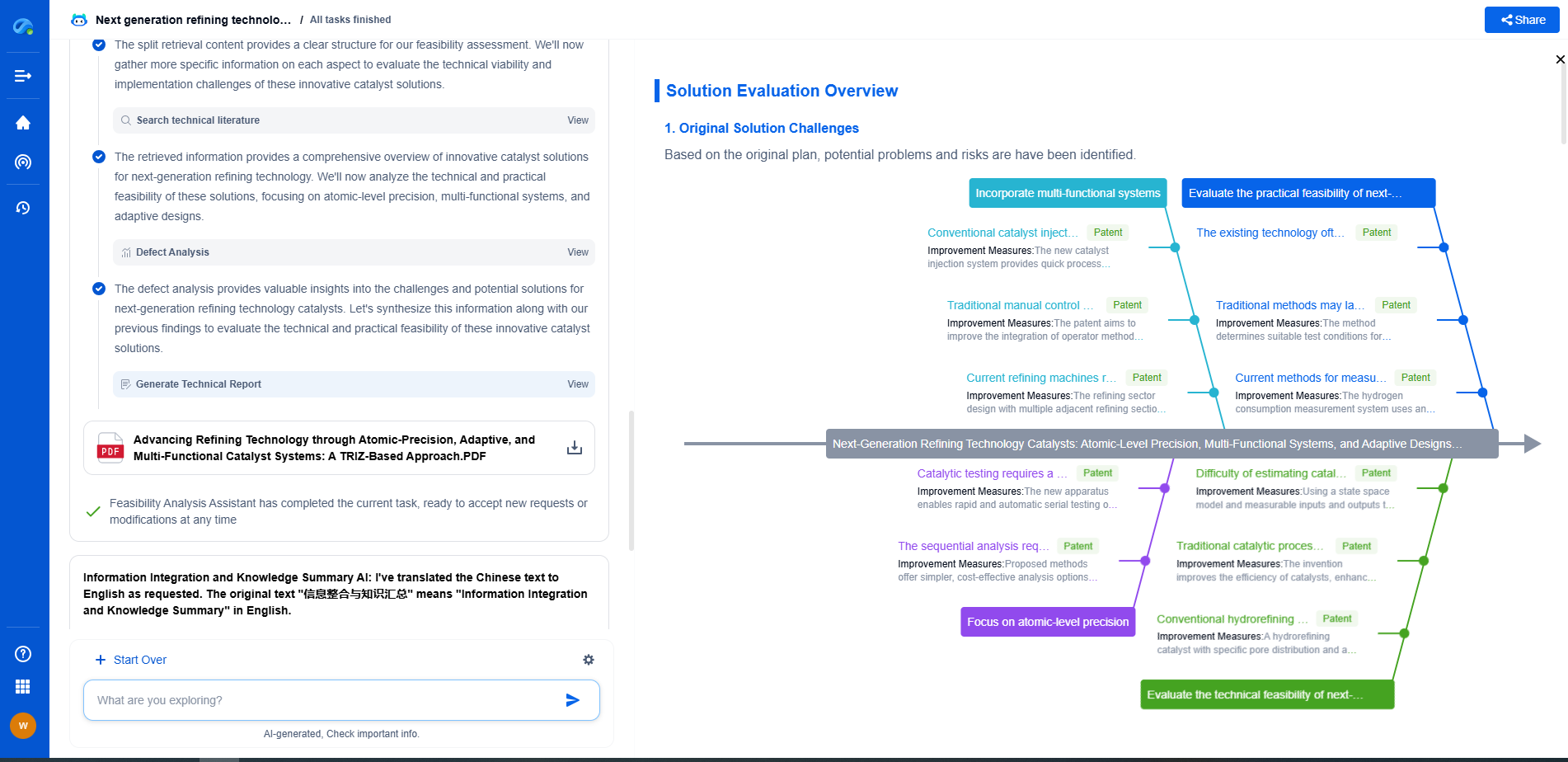
Patsnap Eureka, our intelligent AI assistant built for R&D professionals in high-tech sectors, empowers you with real-time expert-level analysis, technology roadmap exploration, and strategic mapping of core patents—all within a seamless, user-friendly interface.
👉 Experience Patsnap Eureka today and transform how your team navigates the complexity of electromagnetic innovation.
- R&D
- Intellectual Property
- Life Sciences
- Materials
- Tech Scout
- Unparalleled Data Quality
- Higher Quality Content
- 60% Fewer Hallucinations
Browse by: Latest US Patents, China's latest patents, Technical Efficacy Thesaurus, Application Domain, Technology Topic, Popular Technical Reports.
© 2025 PatSnap. All rights reserved.Legal|Privacy policy|Modern Slavery Act Transparency Statement|Sitemap|About US| Contact US: help@patsnap.com

