Why Is My ADC Output Noisy? Tips for Improving Signal Integrity
JUL 17, 2025 |
Analog-to-Digital Converters (ADCs) are essential components in modern electronic systems, converting continuous analog signals into discrete digital data. However, one common issue that engineers and hobbyists encounter is noisy ADC output, which can degrade signal integrity and impact the overall performance of the system. Understanding the sources of this noise is the first step toward mitigating its effects.
Common Sources of ADC Noise
Several factors can contribute to noise in ADC output. Thermal noise, for example, is inherent in all electronic components and is caused by the random motion of electrons. Power supply noise, which can be introduced by fluctuations or ripple in the power source, is another common culprit. Crosstalk from other signals in the system can also lead to noise, as can electromagnetic interference (EMI) from external sources, such as nearby radio frequency (RF) transmitters.
Poor grounding and inadequate decoupling can exacerbate these issues by providing a pathway for noise to couple into the ADC. Additionally, improper PCB layout, such as long traces or inadequate shielding, can increase susceptibility to noise pickup.
Tips for Improving Signal Integrity
1. Optimize Power Supply
A stable power supply is crucial for minimizing ADC noise. Use low-noise voltage regulators and ensure that the power supply is adequately decoupled close to the ADC. Placing decoupling capacitors (such as ceramic capacitors) near the power pins of the ADC can help filter out high-frequency noise. Consider using low-dropout (LDO) regulators if the application’s power requirements allow, as they tend to offer lower noise compared to switching regulators.
2. Implement Good Grounding Practices
Ground loops and poor grounding can introduce significant noise into ADC measurements. A solid ground plane in the PCB design can help reduce impedance and provide a low-noise reference for the ADC. Avoid connecting different ground references directly, and consider using star grounding techniques to minimize potential differences between various ground points in the system.
3. Shielding and Isolation
Electromagnetic interference can be particularly disruptive to ADC performance. Use shielding to isolate sensitive analog paths from digital circuits or other noise sources. Grounded metal enclosures or Faraday cages can be effective in blocking RF interference. For applications where noise is prevalent, consider using differential signaling, which can help reject common-mode noise.
4. Minimize Crosstalk
Crosstalk between signal traces can be reduced by maintaining adequate spacing between them and using separate layers for analog and digital signals on multilayer PCBs. Route high-frequency signals as far away from the ADC inputs as possible. If space is limited, use guard traces connected to ground between sensitive lines.
5. Optimize Sampling Rate and Filter Design
Choosing an appropriate sampling rate can help reduce aliasing and improve signal fidelity. Use anti-aliasing filters to limit bandwidth before the signal reaches the ADC. Low-pass filters can help attenuate high-frequency noise, ensuring that the ADC captures only the desired signal components.
6. Calibrate and Test
Regular calibration of the ADC can help compensate for systematic errors and drift over time. Implement self-test routines to periodically check the ADC performance, and use averaging techniques in the digital domain to reduce random noise.
Conclusion
ADC noise can be a significant challenge in maintaining signal integrity, but with careful attention to design and implementation practices, it can be effectively managed. By optimizing the power supply, grounding, shielding, and filtering, you can significantly reduce noise and improve the reliability of your ADC measurements. As always, thorough testing and iteration are key to achieving the best possible performance in your specific application.
Whether you’re developing multifunctional DAQ platforms, programmable calibration benches, or integrated sensor measurement suites, the ability to track emerging patents, understand competitor strategies, and uncover untapped technology spaces is critical.
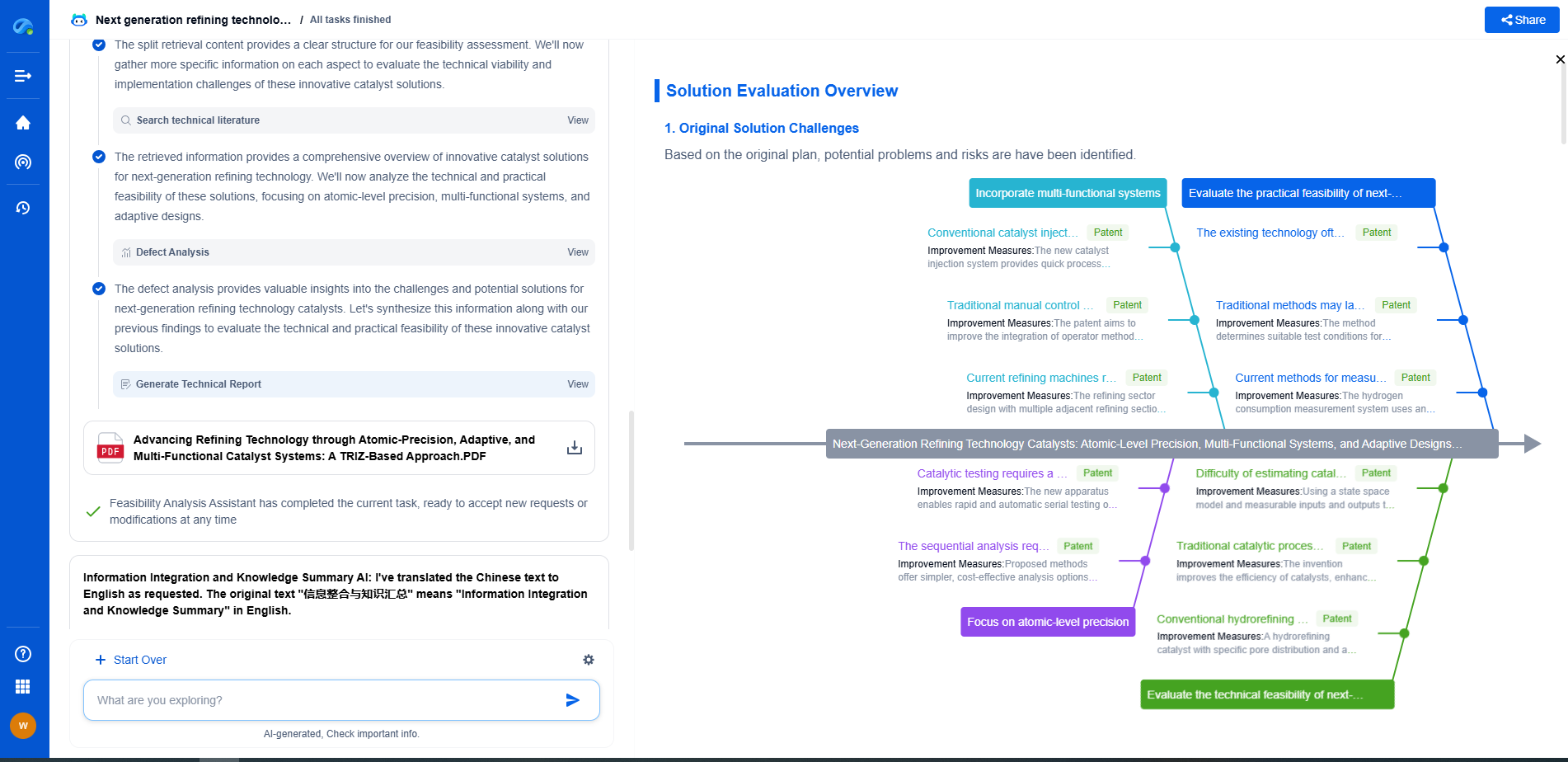
Patsnap Eureka, our intelligent AI assistant built for R&D professionals in high-tech sectors, empowers you with real-time expert-level analysis, technology roadmap exploration, and strategic mapping of core patents—all within a seamless, user-friendly interface.
🧪 Let Eureka be your digital research assistant—streamlining your technical search across disciplines and giving you the clarity to lead confidently. Experience it today.
- R&D
- Intellectual Property
- Life Sciences
- Materials
- Tech Scout
- Unparalleled Data Quality
- Higher Quality Content
- 60% Fewer Hallucinations
Browse by: Latest US Patents, China's latest patents, Technical Efficacy Thesaurus, Application Domain, Technology Topic, Popular Technical Reports.
© 2025 PatSnap. All rights reserved.Legal|Privacy policy|Modern Slavery Act Transparency Statement|Sitemap|About US| Contact US: help@patsnap.com

