
Flange hole center distance detecting tool
A center distance and flange hole technology, applied in the field of industrial product testing and measuring tools, can solve the problems of easy error, high inspection intensity, low efficiency, etc., and achieve the effect of reducing measurement errors, simple operation of inspection tools, and simple structure of inspection tools.
Patent Information
- Authority / Receiving Office
- CN · China
- Patent Type
- Applications(China)
- Current Assignee / Owner
- Publication Date
- 2016-12-14
- Estimated Expiration
- Not applicable · inactive patent
Smart Images
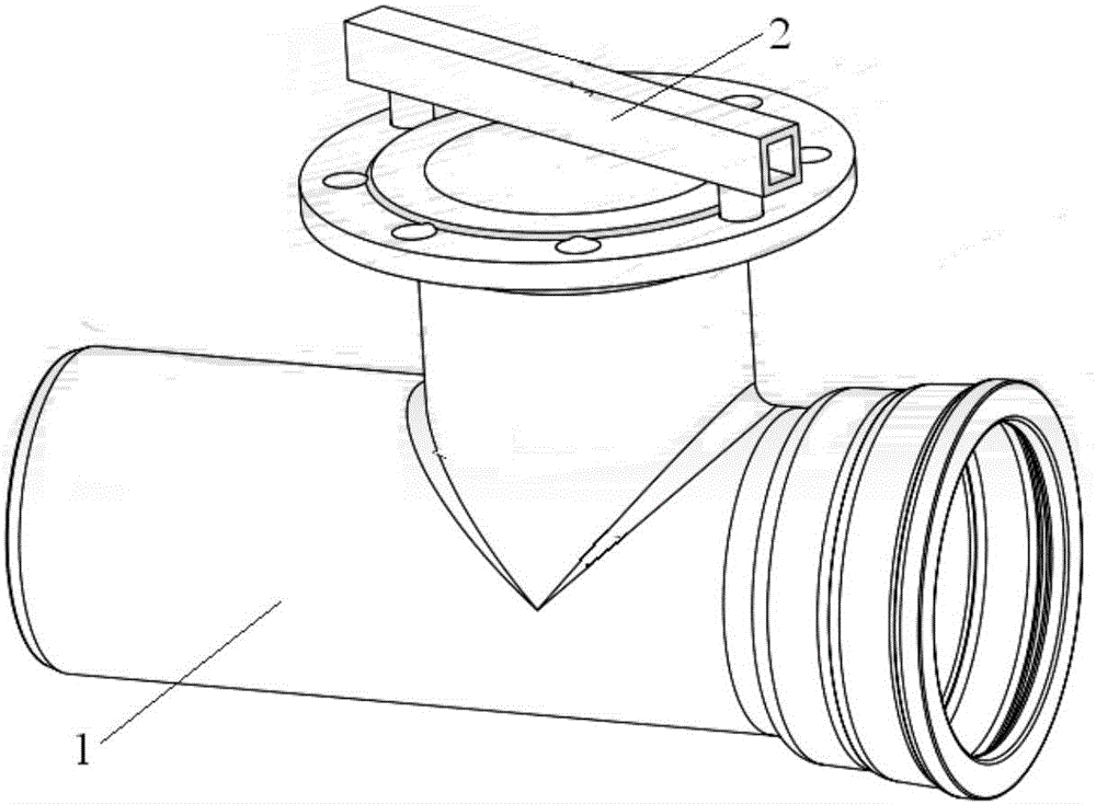
Figure 1 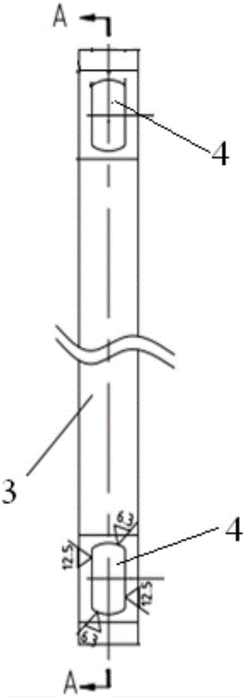
Figure 2 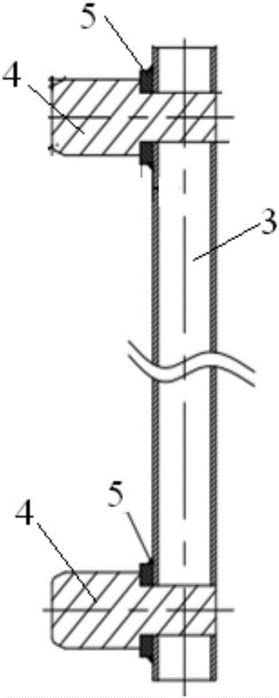
Figure 3
Abstract
Description
technical field
[0001] The invention belongs to the technical field of measuring tools for industrial products. More specifically, the present invention relates to a flange hole center distance checker. Background technique
[0002] In the prior art, a vernier caliper is usually used to measure the center distance, but this method has the following problems:
[0003] 1. Inconvenient operation and low efficiency: When using a vernier caliper to measure the center distance of the flange hole, the result must be recorded after the measurement, and compared with the query standard, so as to determine whether the product is qualified. The center distance of a flange must be tested for multiple sets of holes before it can be judged. The inspection intensity is high and the efficiency is low.
[0004] 2. To measure the center distance of the flange with a vernier caliper, the center distance must be obtained by converting the results of the two measurements of the hole top dista...
Examples
Embodiment Construction
[0023] The specific implementation of the present invention will be described in further detail below by describing the embodiments with reference to the accompanying drawings, so as to help those skilled in the art have a more complete, accurate and in-depth understanding of the inventive concepts and technical solutions of the present invention.
[0024] Such as Figure 1 to Figure 4 The structure of the present invention shown is a flange hole center distance checker, which is used to detect the circumferentially uniform connection hole distance on the connecting flange end surface of the cast pipe 1, and the checker 2 is provided with a checker Specific 3.
[0025] In order to solve the problems existing in the prior art and overcome its defects, realize the invention purpose of improving the detection efficiency and reducing the workload, the technical scheme adopted by the present invention is:
[0026] Such as Figure 1 to Figure 4 As shown, in the flange hole center ...