
Automatic fire fighting system
A fire-fighting system and power shaft technology, which is applied in medical science, dentistry, dental drilling, etc., can solve the problems of on-site fire extinguishing, smoke cannot be blown away, tunnel personnel suffocation and death, etc., and achieve the effect of fast response speed
Patent Information
- Authority / Receiving Office
- CN · China
- Current Assignee / Owner
- Publication Date
- 2019-04-02
- Estimated Expiration
- Not applicable · inactive patent
Smart Images
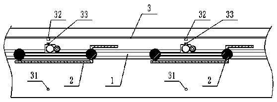
Figure 1 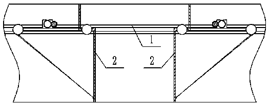
Figure 2 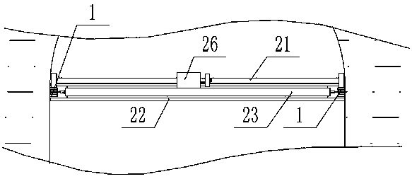
Figure 3
Abstract
Description
technical field
[0001] The invention relates to an automatic fire-fighting system, which belongs to the field of road tunnel fire-fighting equipment. Background technique
[0002] Once a fire breaks out in the tunnel, it is easy to cause traffic congestion. At this time, people and vehicles are in chaos. The fire trucks and fire-fighting equipment in the tunnel cannot quickly extinguish the fire on the spot. people died of suffocation. Contents of the invention
[0003] In order to solve the above-mentioned technical problems, the present invention proposes a special fire-fighting equipment for rapid fire extinguishing and smoke isolation in tunnels.
[0004] In order to achieve the above-mentioned technical purpose, the technical solution provided by the present invention is: an automatic fire-fighting system, including: a track, a barrier plate and an emergency starting device; two tracks are arranged opposite to each other on the two inner walls of the road tunnel, and...
Examples
Embodiment Construction
[0024] Such as Figure 1 to Figure 5 Shown: an automatic fire protection system, including: a track 1, a barrier plate 2 and an emergency start device 3; two tracks 1 are arranged opposite to each other on the two inner walls of the road tunnel, and at least two barriers are arranged on the track 1 board 2;
[0025] The barrier plate 2 includes: an upper baffle plate 21, a lower baffle plate 22, a rotating shaft 23, a power shaft 24, a pull wire shaft 25 and a motor 26; a rotating shaft 23 is slidably arranged between the two rails 1, and on the rotating shaft 23 An upper baffle 21 and a lower baffle 22 are fixed horizontally, the upper baffle 21 is adapted to the cross section of the space above the shaft 23 in the tunnel, and the lower baffle 22 is adapted to the cross section of the space below the shaft 23 in the tunnel When the rotating shaft 23 rotates until the upper baffle plate 21 blocks the space above the rotating shaft 23 in the tunnel, the lower baffle plate 22 c...