
Handgrip for Handlebar
a technology for handlebars and handles, applied in the direction of transportation and packaging, steering devices, cycle equipments, etc., can solve the problems of loosening and unstable hands, and achieve the effect of stable and stable attachment to the handlebars
Patent Information
- Authority / Receiving Office
- US · United States
- Patent Type
- Applications(United States)
- Current Assignee / Owner
- Publication Date
- 2010-10-21
- Estimated Expiration
- Not applicable · inactive patent
Smart Images
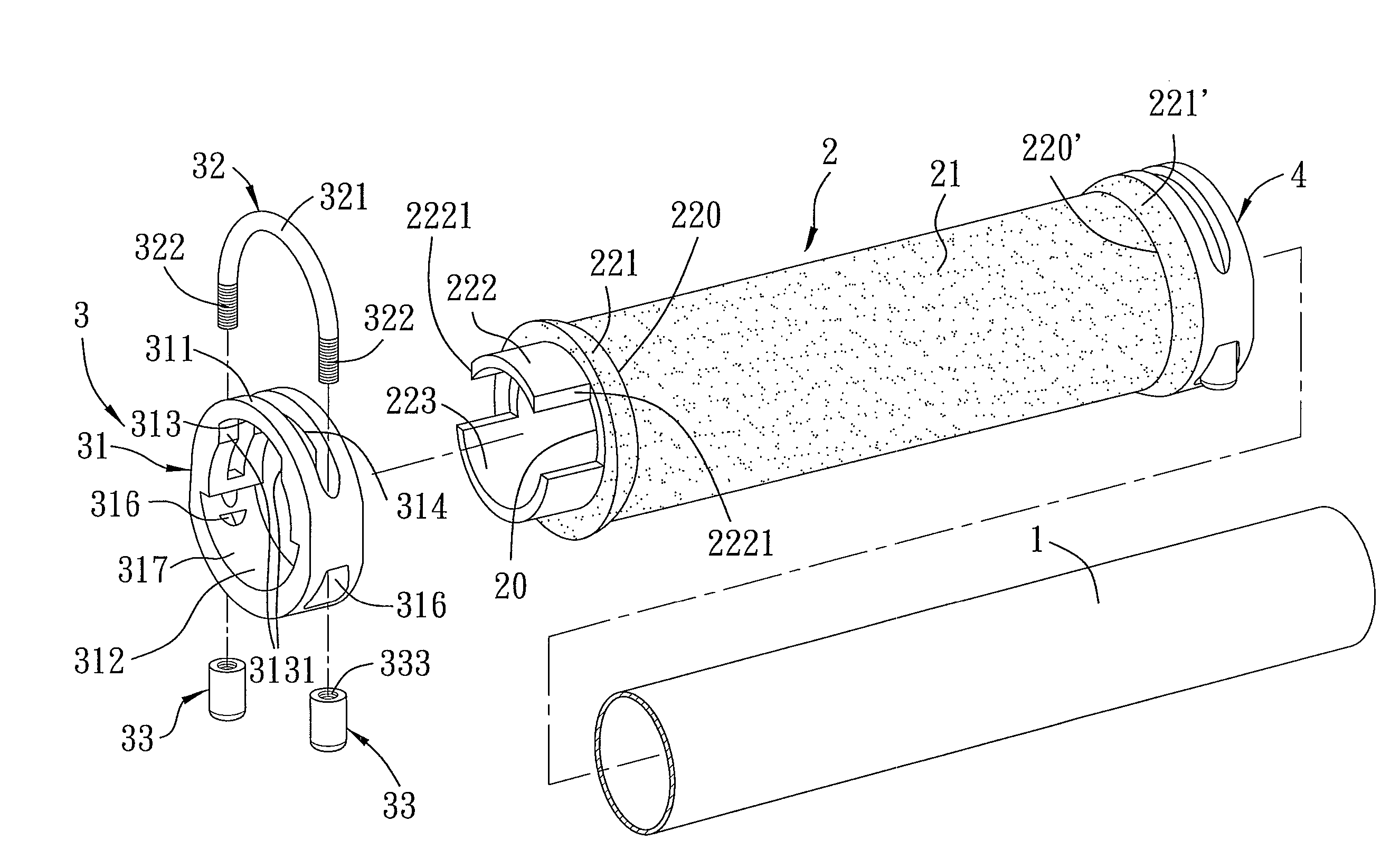
Figure 1 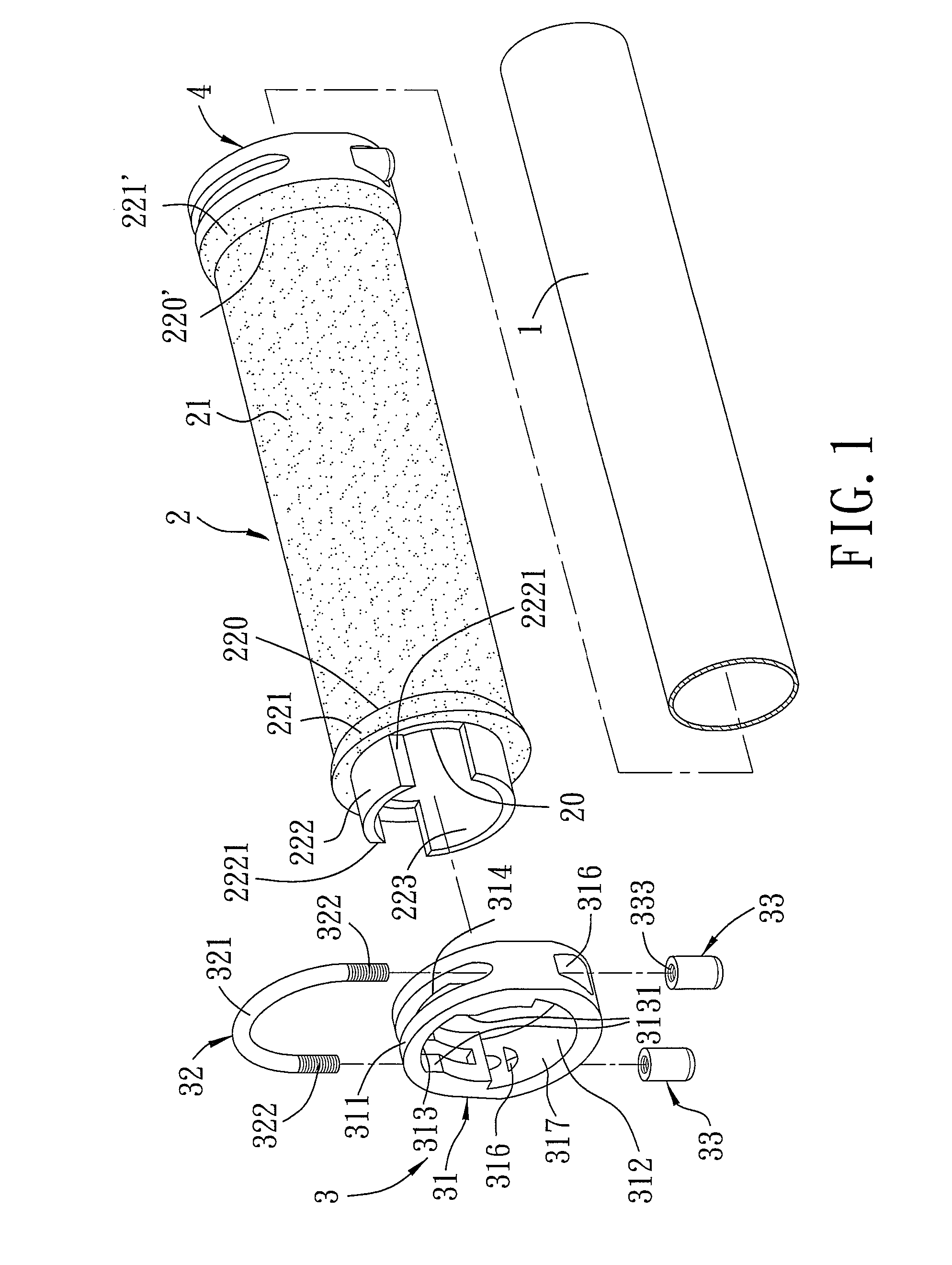
Figure 2 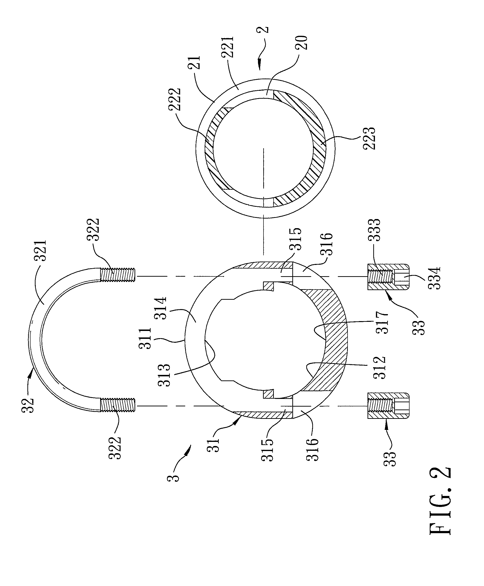
Figure 3
Abstract
Description
CROSS-REFERENCE TO RELATED APPLICATION
[0001] This application claims priority of Taiwanese Application Nos. 098206530 and 098209234 filed respectively on Apr. 20, 2009 and May 26, 2009.BACKGROUND OF THE INVENTION
[0002] 1. Field of the Invention
[0003] This invention relates to a handgrip for a handlebar.
[0004] 2. Description of the Related Art
[0005] A conventional handgrip generally assembled on a handlebar of a vehicle or a movable instrument is soft, and has an anti-slip function. The conventional handgrip is configured simply as a hollow sleeve body sleeved fittingly on the handlebar. Since a fixing unit is not provided between the conventional handgrip and the handlebar, the handgrip and the handlebar are likely to rotate relative to each other. After a period of use, the handgrip will become loose and unstable. To resolve the aforementioned drawback, different kinds of fastening units have been developed to position the handgrip on the handlebar.SUMMARY OF THE INVENTION
[0006] Therefor...
Examples
Embodiment Construction
[0013]A handgrip according to the preferred embodiment of the present invention is adapted to be installed on a handlebar of a vehicle or a movable instrument. In this embodiment, a handlebar 1 of a bicycle is exemplified.
[0014]Referring to FIGS. 1 to 4, the handgrip of the present invention is shown to comprise a tubular grip body 2, a first fastening unit 3, and a second fastening unit 4.
[0015]The tubular grip body 2 is adapted to be sleeved on the handlebar 1, and includes an outer tube 21 having opposite annular first and second ends 220, 220′, and an inner tube 20 inserted fittingly into the outer tube 21 and having at least two angularly spaced-apart resilient clamp portions 222, 223 projecting outwardly and axially from a corresponding one of the first and second ends 220, 220′ (only the clamp portions 222, 223 that project outwardly, oppositely, and axially from the first end 220 is visible in FIG. 1). Each of the first and second ends 220, 220′ has an annular flange 221, 22...