
Headrest for vehicles
a headrest and vehicle technology, applied in the field of headrests, can solve the problems of high cost, complex structure of the headrest disclosed in this publication, and high cost, and achieve the effect of easy fine adjustmen
Patent Information
- Authority / Receiving Office
- US · United States
- Patent Type
- Patents(United States)
- Current Assignee / Owner
- Publication Date
- 2010-05-18
Smart Images
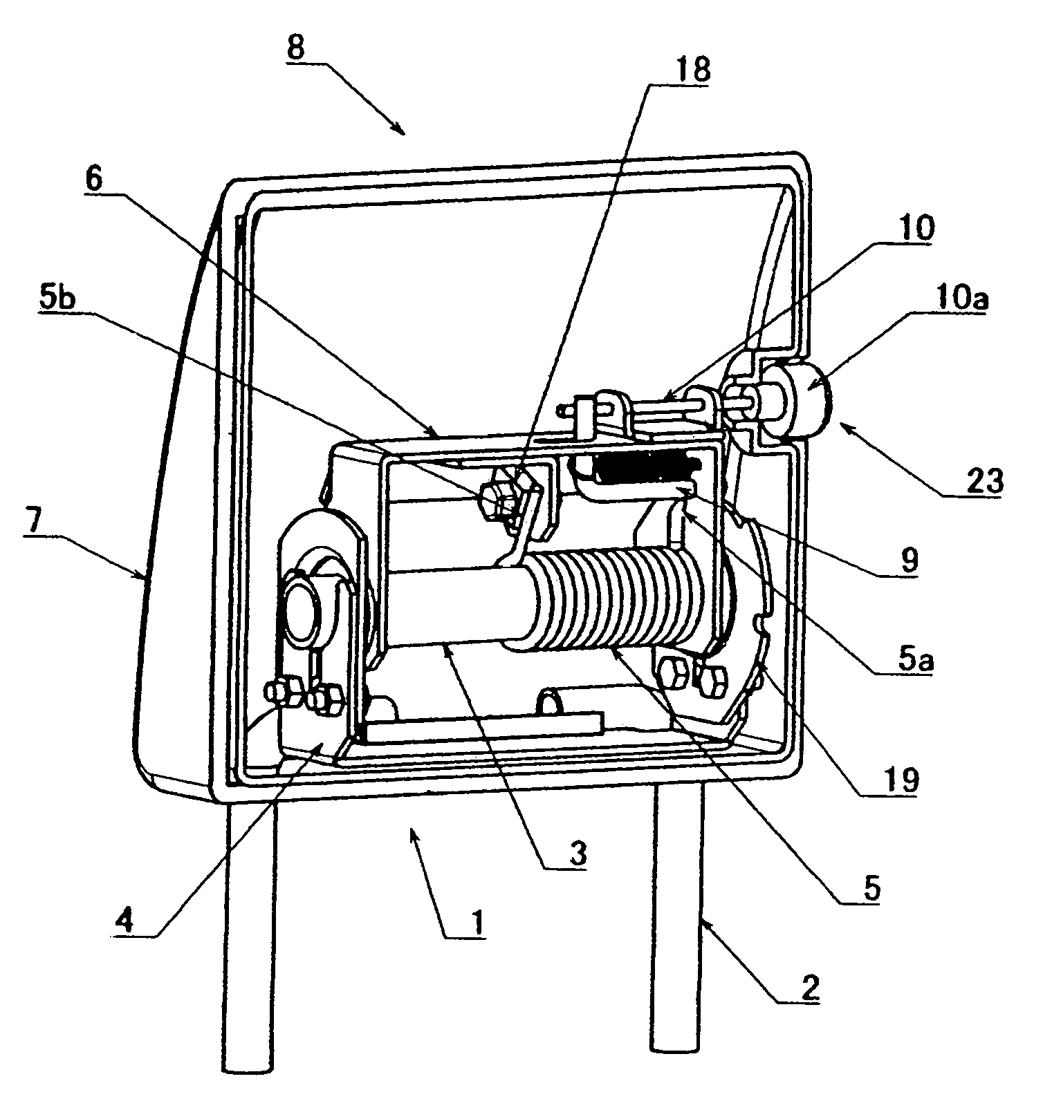
Figure 1 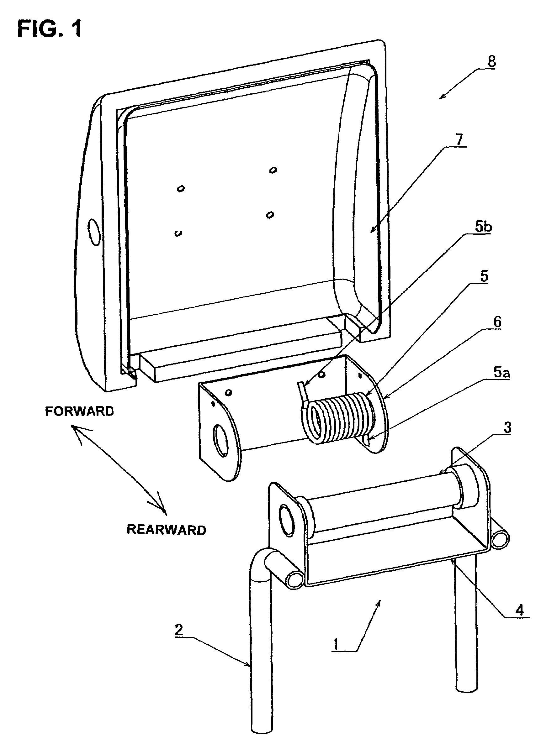
Figure 2 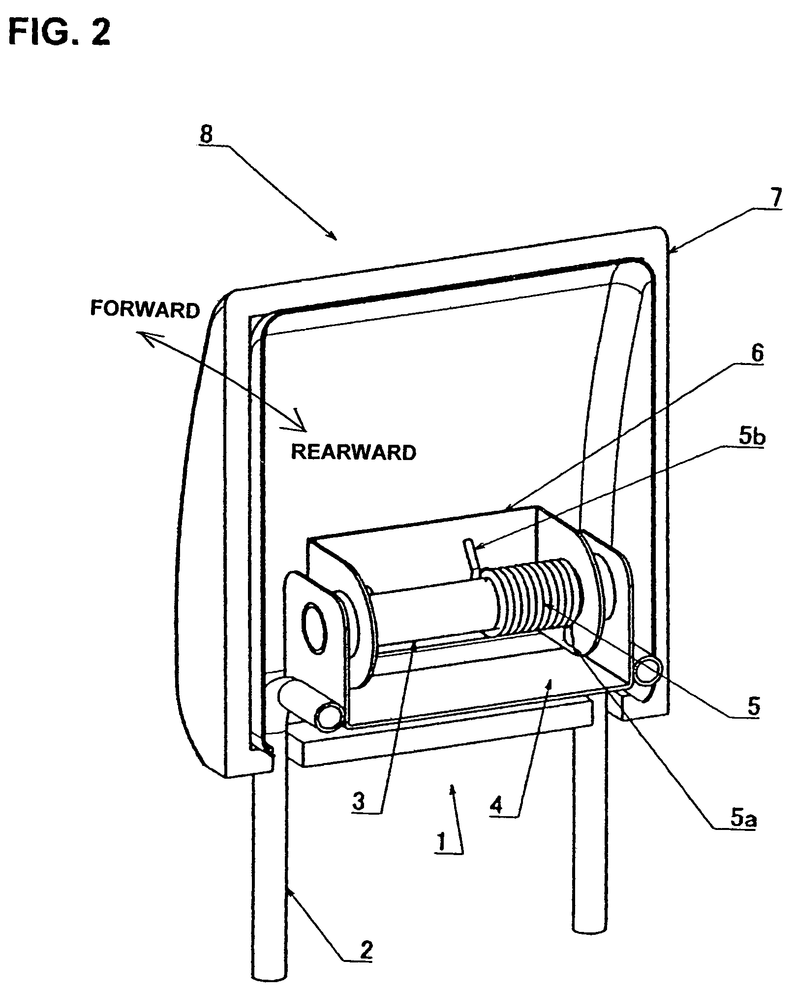
Figure 3
Abstract
Description
BACKGROUND OF THE INVENTION
[0001] 1. Field of the Invention
[0002] The present invention relates to a headrest attached to a seat back of a vehicle seat, and more particularly to a headrest mounted on a seat back for the front passenger seat or rear seat.
[0003] 2. Description of the Related Art
[0004] A headrest will be comfortable if the angle of forward inclination thereof can be finely adjusted to match the passenger's physique or the like. It is also convenient if the sides of the passenger's head are supported together with the back of the head in cases such as when the seat is reclined. Furthermore, if the headrest can be moved forward and rearward, it will be even easier to adjust to the passenger's physique or the like. In addition, for a front passenger seat or a rear seat, when there is no passenger sitting therein, the driver's field of view being blocked can be prevented if the headrest is folded up or retracted. Such a configuration is disclosed in, for example, Japanese Util...
Examples
Embodiment Construction
[0040]Embodiments of the present invention will be now described with reference to the accompanying drawings.
[0041]FIG. 1 is an exploded view of a headrest of the present invention, while FIG. 2 shows the assembled condition thereof. The headrest 8 of this example comprises: an attachment shaft 3 that is secured, so as to be oriented left and right (horizontally), to a stationary plate 4 which is attached integrally to a pair of left and right supporting pillars 2 that are inserted into the upper end of an automobile seat back 1; a base plate 6 that makes a core of a head-receiving member 7 which is fitted on the attachment shaft 3 so that the head-receiving member 7 can turn relative to the attachment shaft 3; and a coil spring 5 that is wound about the attachment shaft 3.
[0042]In this structure, the coil spring 5 is turnable together with the base plate 6, with one end of the coil spring 5 being a free end 5b, and the other end being a fixed end 5a that is secured to the base plat...