
How to Optimize Pressure Drop in Membrane Electrode Assembly
MAR 10, 20269 MIN READ
Generate Your Research Report Instantly with AI Agent
Patsnap Eureka helps you evaluate technical feasibility & market potential.
MEA Pressure Drop Optimization Background and Goals
Membrane Electrode Assembly (MEA) represents the core component of proton exchange membrane fuel cells, where electrochemical reactions occur to convert chemical energy into electrical energy. The MEA consists of a proton exchange membrane sandwiched between two catalyst layers and gas diffusion layers. As fuel cell technology has evolved from laboratory demonstrations to commercial applications, the optimization of MEA performance has become increasingly critical for achieving competitive power density, efficiency, and durability.
Pressure drop optimization within MEA structures has emerged as a fundamental challenge that directly impacts fuel cell system performance and economic viability. Excessive pressure drop across the MEA leads to increased parasitic power consumption by system compressors and blowers, reducing overall system efficiency. Additionally, non-uniform pressure distribution can cause uneven reactant distribution, leading to localized performance degradation and accelerated component aging.
The historical development of MEA technology has progressed through several distinct phases, beginning with early thick membrane designs that prioritized durability over performance. As understanding of transport phenomena advanced, researchers recognized that pressure drop management was essential for scaling fuel cell systems from small laboratory cells to large-scale automotive and stationary applications. The transition from laboratory-scale cells to commercial systems revealed that pressure drop issues become exponentially more challenging as active areas increase and operating pressures rise.
Current market demands for fuel cell systems emphasize the need for MEA designs that can operate efficiently across wide operating ranges while maintaining low manufacturing costs. Automotive applications require MEAs that can handle rapid load changes and varying operating conditions, while stationary applications prioritize long-term durability and consistent performance. These diverse requirements have driven the need for sophisticated pressure drop optimization strategies that balance multiple performance parameters.
The primary technical objectives for MEA pressure drop optimization encompass achieving uniform reactant distribution across large active areas, minimizing parasitic power losses associated with gas compression, and maintaining adequate mass transport rates under high current density operations. These goals must be accomplished while preserving membrane durability, catalyst utilization efficiency, and overall system reliability. The optimization challenge is further complicated by the need to consider manufacturing scalability and cost constraints that are essential for commercial viability.
Pressure drop optimization within MEA structures has emerged as a fundamental challenge that directly impacts fuel cell system performance and economic viability. Excessive pressure drop across the MEA leads to increased parasitic power consumption by system compressors and blowers, reducing overall system efficiency. Additionally, non-uniform pressure distribution can cause uneven reactant distribution, leading to localized performance degradation and accelerated component aging.
The historical development of MEA technology has progressed through several distinct phases, beginning with early thick membrane designs that prioritized durability over performance. As understanding of transport phenomena advanced, researchers recognized that pressure drop management was essential for scaling fuel cell systems from small laboratory cells to large-scale automotive and stationary applications. The transition from laboratory-scale cells to commercial systems revealed that pressure drop issues become exponentially more challenging as active areas increase and operating pressures rise.
Current market demands for fuel cell systems emphasize the need for MEA designs that can operate efficiently across wide operating ranges while maintaining low manufacturing costs. Automotive applications require MEAs that can handle rapid load changes and varying operating conditions, while stationary applications prioritize long-term durability and consistent performance. These diverse requirements have driven the need for sophisticated pressure drop optimization strategies that balance multiple performance parameters.
The primary technical objectives for MEA pressure drop optimization encompass achieving uniform reactant distribution across large active areas, minimizing parasitic power losses associated with gas compression, and maintaining adequate mass transport rates under high current density operations. These goals must be accomplished while preserving membrane durability, catalyst utilization efficiency, and overall system reliability. The optimization challenge is further complicated by the need to consider manufacturing scalability and cost constraints that are essential for commercial viability.
Market Demand for High-Performance MEA Systems
The global fuel cell market is experiencing unprecedented growth, driven by the urgent need for clean energy solutions and decarbonization initiatives across multiple industries. This expansion has created substantial demand for high-performance membrane electrode assemblies, which serve as the critical heart of fuel cell systems. The automotive sector represents the largest growth driver, with major manufacturers investing heavily in hydrogen fuel cell vehicles as a complement to battery electric vehicles for long-range and heavy-duty applications.
Industrial applications are emerging as another significant demand driver, particularly in sectors requiring reliable backup power, material handling equipment, and stationary power generation. Data centers, telecommunications infrastructure, and critical facilities increasingly seek fuel cell solutions that offer superior reliability compared to traditional backup systems. The maritime and aerospace industries are also exploring fuel cell technologies for zero-emission propulsion systems, creating new market segments with stringent performance requirements.
The demand for optimized pressure drop characteristics in MEA systems stems from the direct correlation between pressure losses and overall system efficiency. End users across all application segments are demanding fuel cell systems that maximize power output while minimizing parasitic losses from auxiliary components such as air compressors and hydrogen recirculation pumps. Lower pressure drop requirements translate to reduced energy consumption by these balance-of-plant components, improving overall system efficiency and reducing operational costs.
Commercial vehicle manufacturers particularly emphasize the importance of pressure drop optimization, as it directly impacts vehicle range and operational economics. Fleet operators require fuel cell systems that can deliver consistent performance across varying load conditions while maintaining minimal pressure losses that would otherwise reduce driving range or increase hydrogen consumption.
The growing emphasis on system-level optimization has shifted market preferences toward MEA designs that integrate advanced flow field geometries, optimized gas diffusion layers, and innovative membrane technologies. Customers increasingly evaluate MEA performance based on comprehensive metrics that include pressure drop characteristics alongside traditional parameters such as power density and durability. This holistic approach to performance evaluation is driving suppliers to develop integrated solutions that address multiple performance criteria simultaneously.
Market demand is also influenced by evolving regulatory frameworks and performance standards that emphasize overall system efficiency. Government incentives and procurement programs increasingly consider total cost of ownership metrics, which include operational efficiency factors directly related to pressure drop optimization. This regulatory environment is accelerating the adoption of advanced MEA technologies that demonstrate superior pressure management capabilities.
Industrial applications are emerging as another significant demand driver, particularly in sectors requiring reliable backup power, material handling equipment, and stationary power generation. Data centers, telecommunications infrastructure, and critical facilities increasingly seek fuel cell solutions that offer superior reliability compared to traditional backup systems. The maritime and aerospace industries are also exploring fuel cell technologies for zero-emission propulsion systems, creating new market segments with stringent performance requirements.
The demand for optimized pressure drop characteristics in MEA systems stems from the direct correlation between pressure losses and overall system efficiency. End users across all application segments are demanding fuel cell systems that maximize power output while minimizing parasitic losses from auxiliary components such as air compressors and hydrogen recirculation pumps. Lower pressure drop requirements translate to reduced energy consumption by these balance-of-plant components, improving overall system efficiency and reducing operational costs.
Commercial vehicle manufacturers particularly emphasize the importance of pressure drop optimization, as it directly impacts vehicle range and operational economics. Fleet operators require fuel cell systems that can deliver consistent performance across varying load conditions while maintaining minimal pressure losses that would otherwise reduce driving range or increase hydrogen consumption.
The growing emphasis on system-level optimization has shifted market preferences toward MEA designs that integrate advanced flow field geometries, optimized gas diffusion layers, and innovative membrane technologies. Customers increasingly evaluate MEA performance based on comprehensive metrics that include pressure drop characteristics alongside traditional parameters such as power density and durability. This holistic approach to performance evaluation is driving suppliers to develop integrated solutions that address multiple performance criteria simultaneously.
Market demand is also influenced by evolving regulatory frameworks and performance standards that emphasize overall system efficiency. Government incentives and procurement programs increasingly consider total cost of ownership metrics, which include operational efficiency factors directly related to pressure drop optimization. This regulatory environment is accelerating the adoption of advanced MEA technologies that demonstrate superior pressure management capabilities.
Current MEA Pressure Drop Challenges and Limitations
Membrane Electrode Assembly pressure drop challenges represent one of the most critical bottlenecks in fuel cell performance optimization. Current MEA designs face significant limitations in achieving optimal balance between electrochemical performance and fluid dynamics efficiency. The primary challenge stems from the inherent trade-off between maximizing active surface area for electrochemical reactions and minimizing resistance to reactant flow through the assembly.
Gas diffusion layer porosity and tortuosity present fundamental constraints in existing MEA architectures. Traditional carbon fiber-based GDLs exhibit heterogeneous pore structures that create uneven pressure distributions across the electrode surface. This non-uniformity leads to localized high-pressure zones that impede reactant transport and contribute to overall system inefficiency. The microporous layer integration further complicates flow dynamics by introducing additional resistance pathways.
Catalyst layer thickness optimization remains a persistent challenge in current MEA designs. Thicker catalyst layers provide increased electrochemically active surface area but simultaneously create longer diffusion pathways for reactants. This geometric constraint results in concentration gradients that become more pronounced under high current density operations, leading to performance degradation and increased pressure drop penalties.
Membrane thickness and ionic conductivity limitations compound pressure drop challenges in contemporary MEA configurations. Proton exchange membranes must maintain adequate mechanical strength while minimizing ohmic resistance, but current materials struggle to achieve optimal thickness without compromising structural integrity. Thinner membranes reduce ionic resistance but increase susceptibility to mechanical failure under pressure differentials.
Flow field design integration with MEA components creates additional pressure drop complications. Current bipolar plate channel geometries often fail to account for MEA-specific flow characteristics, resulting in suboptimal pressure distribution patterns. The interface between flow channels and gas diffusion layers frequently generates turbulence and flow separation phenomena that increase parasitic pressure losses.
Temperature and humidity management within MEA structures introduces dynamic pressure drop variations that current designs inadequately address. Water management challenges create localized flooding conditions that dramatically increase flow resistance, while dry-out conditions lead to membrane degradation and altered flow patterns. These transient effects make pressure drop optimization particularly challenging under real-world operating conditions.
Manufacturing tolerances and assembly variations in current MEA production processes contribute to inconsistent pressure drop characteristics. Compression levels, material alignment, and interfacial contact quality vary significantly between units, creating unpredictable performance variations that complicate system-level optimization efforts and limit the effectiveness of standardized pressure drop mitigation strategies.
Gas diffusion layer porosity and tortuosity present fundamental constraints in existing MEA architectures. Traditional carbon fiber-based GDLs exhibit heterogeneous pore structures that create uneven pressure distributions across the electrode surface. This non-uniformity leads to localized high-pressure zones that impede reactant transport and contribute to overall system inefficiency. The microporous layer integration further complicates flow dynamics by introducing additional resistance pathways.
Catalyst layer thickness optimization remains a persistent challenge in current MEA designs. Thicker catalyst layers provide increased electrochemically active surface area but simultaneously create longer diffusion pathways for reactants. This geometric constraint results in concentration gradients that become more pronounced under high current density operations, leading to performance degradation and increased pressure drop penalties.
Membrane thickness and ionic conductivity limitations compound pressure drop challenges in contemporary MEA configurations. Proton exchange membranes must maintain adequate mechanical strength while minimizing ohmic resistance, but current materials struggle to achieve optimal thickness without compromising structural integrity. Thinner membranes reduce ionic resistance but increase susceptibility to mechanical failure under pressure differentials.
Flow field design integration with MEA components creates additional pressure drop complications. Current bipolar plate channel geometries often fail to account for MEA-specific flow characteristics, resulting in suboptimal pressure distribution patterns. The interface between flow channels and gas diffusion layers frequently generates turbulence and flow separation phenomena that increase parasitic pressure losses.
Temperature and humidity management within MEA structures introduces dynamic pressure drop variations that current designs inadequately address. Water management challenges create localized flooding conditions that dramatically increase flow resistance, while dry-out conditions lead to membrane degradation and altered flow patterns. These transient effects make pressure drop optimization particularly challenging under real-world operating conditions.
Manufacturing tolerances and assembly variations in current MEA production processes contribute to inconsistent pressure drop characteristics. Compression levels, material alignment, and interfacial contact quality vary significantly between units, creating unpredictable performance variations that complicate system-level optimization efforts and limit the effectiveness of standardized pressure drop mitigation strategies.
Existing MEA Pressure Drop Reduction Solutions
01 Flow field design optimization for pressure drop reduction
The design and configuration of flow fields in membrane electrode assemblies can significantly impact pressure drop. Optimized flow channel geometries, including channel width, depth, and pattern arrangements, can minimize resistance to reactant flow while maintaining uniform distribution. Advanced flow field designs such as serpentine, parallel, or interdigitated patterns are employed to balance pressure drop with mass transport efficiency.- Flow field design optimization for pressure drop reduction: The design of flow fields in membrane electrode assemblies can be optimized to reduce pressure drop across the system. This includes modifications to channel geometry, dimensions, and patterns to improve fluid distribution and minimize flow resistance. Serpentine, parallel, and interdigitated flow field configurations can be engineered to balance pressure drop with reactant distribution efficiency.
- Gas diffusion layer structure and porosity control: The structure and porosity of gas diffusion layers significantly impact pressure drop in membrane electrode assemblies. Optimizing pore size distribution, thickness, and material composition of the diffusion layer can reduce flow resistance while maintaining adequate mass transport. The use of microporous layers and gradient porosity structures helps achieve lower pressure drop without compromising performance.
- Manifold and inlet/outlet configuration: The design of manifolds and inlet/outlet configurations plays a crucial role in managing pressure drop across membrane electrode assemblies. Proper sizing and positioning of inlet and outlet ports, along with optimized manifold geometry, can ensure uniform flow distribution and minimize pressure losses. Header designs that promote even flow distribution across multiple channels help reduce overall system pressure drop.
- Membrane thickness and compression optimization: The thickness and compression level of the membrane in the assembly directly affects pressure drop characteristics. Thinner membranes generally result in lower pressure drop but must be balanced with mechanical stability and durability requirements. Optimizing compression force during assembly ensures proper sealing while minimizing excessive compression that could increase flow resistance through the porous layers.
- Bipolar plate channel design and surface treatment: Bipolar plate channel design and surface characteristics significantly influence pressure drop in membrane electrode assemblies. Channel depth, width, rib dimensions, and surface roughness all contribute to flow resistance. Surface treatments and coatings can reduce friction and improve flow characteristics, while optimized channel cross-sections minimize pressure losses during operation.
02 Gas diffusion layer structure and porosity control
The gas diffusion layer plays a critical role in managing pressure drop across the membrane electrode assembly. Controlling the porosity, thickness, and pore size distribution of the gas diffusion layer can optimize the balance between gas permeability and mechanical support. Materials with tailored microstructures enable reduced pressure drop while maintaining adequate water management and electrical conductivity.Expand Specific Solutions03 Membrane thickness and compression optimization
The thickness and compression level of the membrane electrode assembly directly affect pressure drop characteristics. Thinner membranes and optimized compression ratios can reduce flow resistance while maintaining mechanical integrity and sealing performance. Proper compression control ensures uniform contact between components without excessive pressure drop or performance degradation.Expand Specific Solutions04 Bipolar plate channel configuration and surface treatment
Bipolar plate design, including channel geometry and surface characteristics, significantly influences pressure drop in fuel cell systems. Surface treatments and coatings can reduce friction and improve flow characteristics. Channel cross-sectional shapes, rib-to-channel ratios, and manifold designs are optimized to minimize pressure losses while ensuring adequate reactant distribution and product removal.Expand Specific Solutions05 Sealing and edge compression management
Proper sealing and edge compression in membrane electrode assemblies affect both sealing performance and pressure drop. Gasket design, seal material selection, and compression force distribution at the assembly edges influence flow resistance and uniformity. Optimized sealing strategies prevent leakage while minimizing unnecessary flow restrictions that could increase pressure drop across the assembly.Expand Specific Solutions
Key Players in MEA and Fuel Cell Industry
The membrane electrode assembly (MEA) pressure drop optimization field represents a mature technology sector within the broader fuel cell industry, currently experiencing significant growth driven by automotive electrification and clean energy transitions. Major automotive manufacturers including Toyota, Nissan, Hyundai, Honda, and General Motors are actively developing fuel cell vehicles, while specialized companies like BASF Fuel Cell GmbH, VINATECH, and Shanghai Shen-Li High Tech focus specifically on MEA technologies. The technology maturity varies across players, with established automotive giants leveraging decades of R&D experience and partnerships with material science companies like Toray Industries, 3M, and W.L. Gore & Associates who provide advanced membrane materials. Research institutions such as Forschungszentrum Jülich and Tsinghua University contribute fundamental research, while the market shows strong growth potential as fuel cell adoption accelerates globally, particularly in transportation and stationary power applications.
Toyota Motor Corp.
Technical Solution: Toyota has developed advanced MEA designs focusing on optimized flow field patterns and channel geometries to minimize pressure drop while maintaining uniform reactant distribution. Their approach includes implementing serpentine flow channels with variable cross-sections and strategic placement of gas diffusion layers with tailored porosity gradients. The company utilizes computational fluid dynamics modeling to optimize the balance between mass transport and pressure losses, incorporating micro-porous layers with controlled thickness to reduce resistance while ensuring adequate water management and gas permeability across the membrane electrode assembly.
Strengths: Extensive automotive fuel cell experience, proven mass production capabilities, integrated system optimization. Weaknesses: Conservative approach may limit breakthrough innovations, focus primarily on automotive applications.
Robert Bosch GmbH
Technical Solution: Bosch employs a systematic approach to pressure drop optimization through advanced MEA architecture featuring engineered flow field designs with parallel and interdigitated channel configurations. Their technology focuses on reducing parasitic losses by optimizing catalyst layer thickness, implementing gradient porosity gas diffusion layers, and developing novel bipolar plate designs with reduced channel resistance. The company integrates machine learning algorithms to predict optimal operating conditions and has developed proprietary coating techniques for catalyst layers that minimize transport resistance while maximizing electrochemical active surface area.
Strengths: Strong engineering expertise, comprehensive fuel cell system integration, advanced manufacturing processes. Weaknesses: Limited market presence in stationary applications, dependency on automotive market cycles.
Core Innovations in MEA Flow Field Design
Sealing-integrated membrane electrode assembly
PatentInactiveJP2008171615A
Innovation
- A membrane electrode assembly with a sealing gasket offset towards the anode electrode side, combined with gas channel bodies of varying thicknesses and a corrugated plate structure, to adjust and reduce pressure loss in the gas flow paths.


Liquid degassing membrane contactors, components, systems and related methods
PatentActiveUS20120247337A1
Innovation
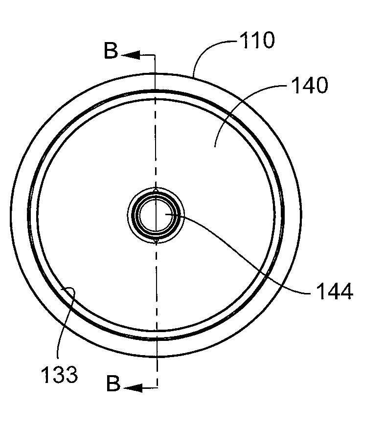
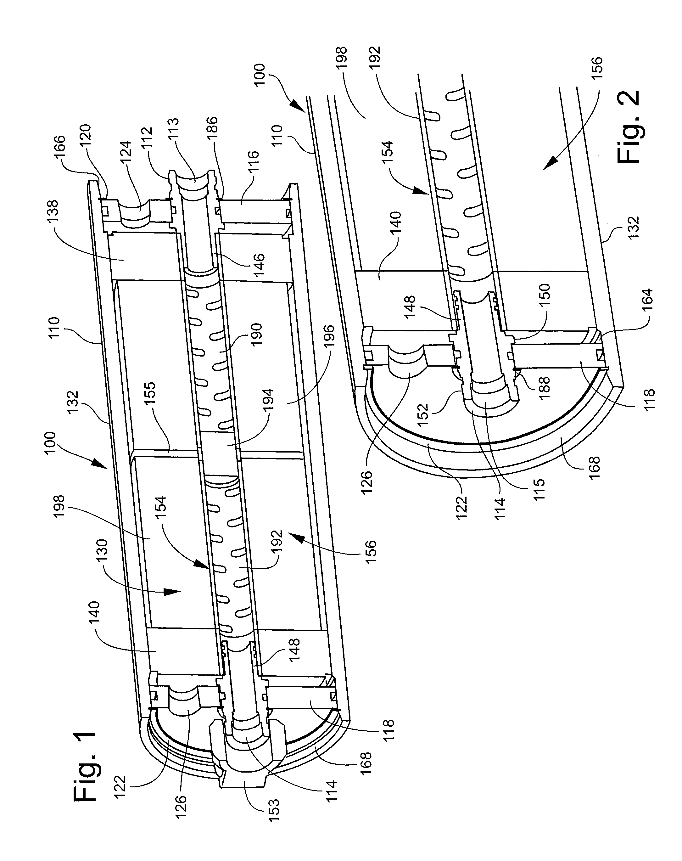
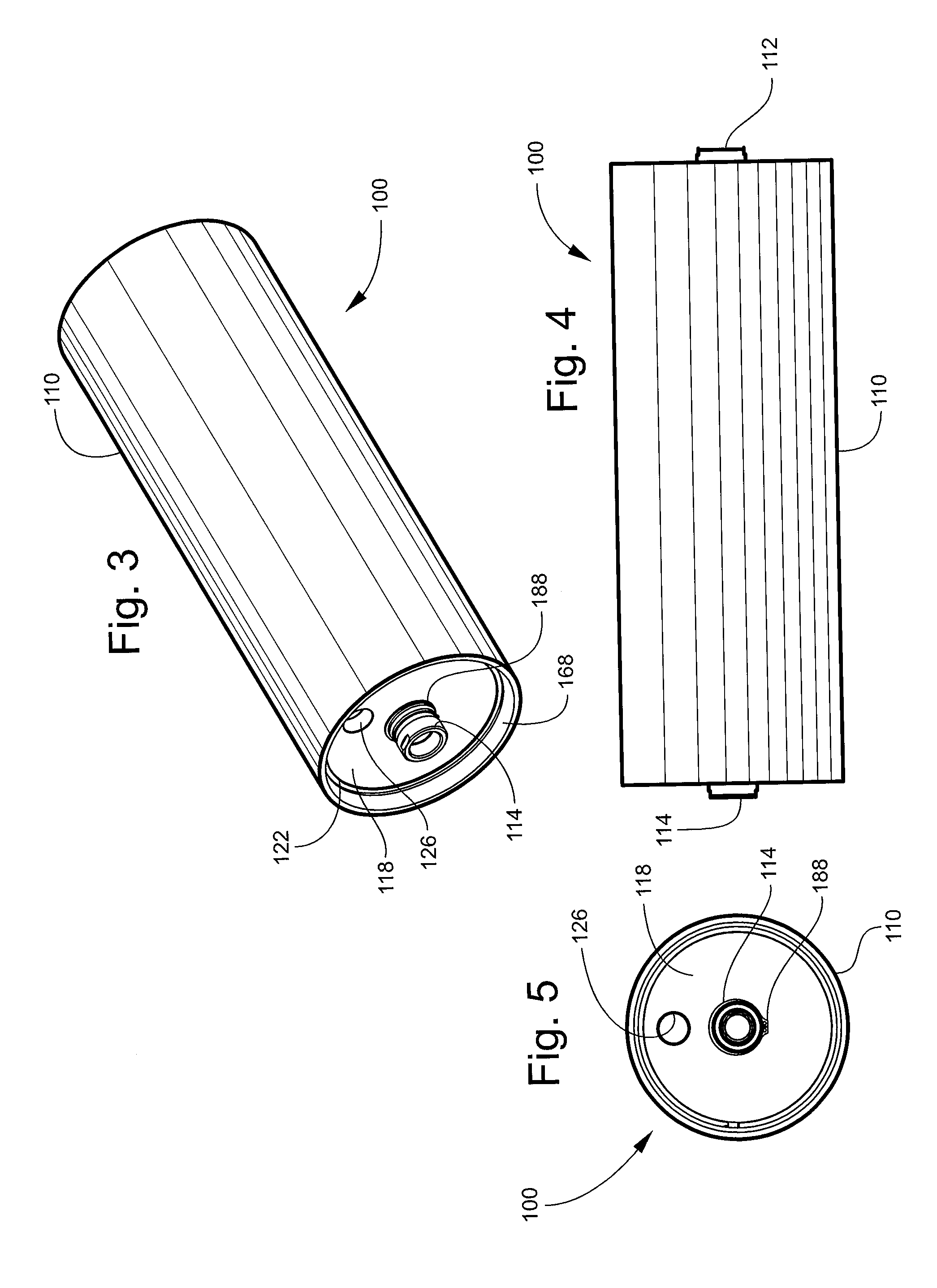
- A new membrane contactor design featuring a cylindrical housing with integrally potted hollow fiber membranes, planar disc-shaped end caps, and a perforated core, which allows for modular, lightweight, and cost-effective degassing using a sweep gas or vacuum, eliminating the need for bolts and v-band clamps, and utilizing materials like PVC and stainless steel for durability and corrosion resistance.

Environmental Standards for Fuel Cell Applications
Environmental standards for fuel cell applications play a critical role in optimizing pressure drop within membrane electrode assemblies (MEAs). These standards establish the operational parameters and testing conditions that directly influence MEA design decisions, particularly regarding flow field geometry, material selection, and manufacturing tolerances that affect pressure drop characteristics.
The International Electrotechnical Commission (IEC) 62282 series and the Society of Automotive Engineers (SAE) J2615 standard define specific environmental testing requirements for fuel cells, including temperature cycling, humidity variations, and vibration resistance. These conditions significantly impact MEA performance and pressure drop optimization strategies, as materials must maintain structural integrity and dimensional stability across wide operating ranges.
Temperature-related standards are particularly relevant to pressure drop optimization. Operating temperatures between -40°C and 85°C, as specified in automotive applications, affect membrane hydration levels and gas viscosity, both critical factors in pressure drop calculations. Higher temperatures reduce gas viscosity but may compromise membrane conductivity, requiring careful balance in flow field design to maintain optimal pressure differentials.
Humidity standards present additional challenges for MEA pressure drop optimization. Environmental requirements for relative humidity ranging from 5% to 95% directly influence membrane swelling and shrinkage, affecting the mechanical compression of gas diffusion layers and subsequent pressure drop characteristics. Proper MEA design must accommodate these dimensional changes while maintaining consistent flow distribution.
Vibration and shock resistance standards, particularly relevant for mobile applications, impose constraints on MEA assembly methods and material choices. These requirements influence the selection of gasket materials and compression levels, which are fundamental parameters in pressure drop optimization. Excessive compression to meet environmental durability may increase pressure drop, while insufficient compression may compromise sealing performance.
Contamination resistance standards also impact pressure drop optimization strategies. Requirements for tolerance to airborne contaminants and fuel impurities necessitate the incorporation of filtration considerations into MEA design, potentially affecting overall system pressure drop budgets and requiring compensation through optimized internal flow geometries.
The International Electrotechnical Commission (IEC) 62282 series and the Society of Automotive Engineers (SAE) J2615 standard define specific environmental testing requirements for fuel cells, including temperature cycling, humidity variations, and vibration resistance. These conditions significantly impact MEA performance and pressure drop optimization strategies, as materials must maintain structural integrity and dimensional stability across wide operating ranges.
Temperature-related standards are particularly relevant to pressure drop optimization. Operating temperatures between -40°C and 85°C, as specified in automotive applications, affect membrane hydration levels and gas viscosity, both critical factors in pressure drop calculations. Higher temperatures reduce gas viscosity but may compromise membrane conductivity, requiring careful balance in flow field design to maintain optimal pressure differentials.
Humidity standards present additional challenges for MEA pressure drop optimization. Environmental requirements for relative humidity ranging from 5% to 95% directly influence membrane swelling and shrinkage, affecting the mechanical compression of gas diffusion layers and subsequent pressure drop characteristics. Proper MEA design must accommodate these dimensional changes while maintaining consistent flow distribution.
Vibration and shock resistance standards, particularly relevant for mobile applications, impose constraints on MEA assembly methods and material choices. These requirements influence the selection of gasket materials and compression levels, which are fundamental parameters in pressure drop optimization. Excessive compression to meet environmental durability may increase pressure drop, while insufficient compression may compromise sealing performance.
Contamination resistance standards also impact pressure drop optimization strategies. Requirements for tolerance to airborne contaminants and fuel impurities necessitate the incorporation of filtration considerations into MEA design, potentially affecting overall system pressure drop budgets and requiring compensation through optimized internal flow geometries.
Manufacturing Scalability for Optimized MEA Designs
Manufacturing scalability represents a critical bottleneck in translating optimized MEA designs from laboratory prototypes to commercial production volumes. The transition from small-scale research environments to industrial manufacturing introduces numerous challenges that can significantly impact the pressure drop characteristics originally achieved in optimized designs. Current manufacturing processes often struggle to maintain the precise structural parameters and material distributions that are essential for pressure drop optimization.
The scalability challenge primarily stems from the difficulty in replicating the exact pore structures, catalyst layer uniformity, and membrane-electrode interfaces that contribute to optimal pressure drop performance. Laboratory-scale MEA fabrication typically employs batch processes with high precision control, allowing for fine-tuning of parameters such as catalyst loading gradients, pore size distributions, and interfacial contact resistance. However, scaling these processes to continuous manufacturing lines introduces variability that can compromise the carefully optimized pressure drop characteristics.
Roll-to-roll manufacturing processes present both opportunities and challenges for maintaining pressure drop optimization at scale. While these continuous processes offer the potential for high-volume production, they require sophisticated process control systems to ensure consistent catalyst deposition, membrane handling, and hot-pressing conditions across large surface areas. Variations in web tension, temperature uniformity, and coating thickness can lead to non-uniform pressure drop characteristics across individual MEAs and between production batches.
Quality control and process monitoring become increasingly complex when scaling optimized MEA designs. Traditional quality assessment methods may not adequately capture the subtle variations in microstructure that significantly impact pressure drop performance. Advanced in-line monitoring techniques, including real-time impedance measurements and optical inspection systems, are essential for maintaining the tight tolerances required for pressure drop optimization during high-volume manufacturing.
The economic considerations of manufacturing scalability often conflict with the requirements for pressure drop optimization. Cost reduction pressures may drive manufacturers toward simplified designs or less expensive materials that compromise optimal pressure drop characteristics. Balancing manufacturing efficiency with performance requirements necessitates careful consideration of design modifications that maintain pressure drop benefits while enabling cost-effective production processes.
The scalability challenge primarily stems from the difficulty in replicating the exact pore structures, catalyst layer uniformity, and membrane-electrode interfaces that contribute to optimal pressure drop performance. Laboratory-scale MEA fabrication typically employs batch processes with high precision control, allowing for fine-tuning of parameters such as catalyst loading gradients, pore size distributions, and interfacial contact resistance. However, scaling these processes to continuous manufacturing lines introduces variability that can compromise the carefully optimized pressure drop characteristics.
Roll-to-roll manufacturing processes present both opportunities and challenges for maintaining pressure drop optimization at scale. While these continuous processes offer the potential for high-volume production, they require sophisticated process control systems to ensure consistent catalyst deposition, membrane handling, and hot-pressing conditions across large surface areas. Variations in web tension, temperature uniformity, and coating thickness can lead to non-uniform pressure drop characteristics across individual MEAs and between production batches.
Quality control and process monitoring become increasingly complex when scaling optimized MEA designs. Traditional quality assessment methods may not adequately capture the subtle variations in microstructure that significantly impact pressure drop performance. Advanced in-line monitoring techniques, including real-time impedance measurements and optical inspection systems, are essential for maintaining the tight tolerances required for pressure drop optimization during high-volume manufacturing.
The economic considerations of manufacturing scalability often conflict with the requirements for pressure drop optimization. Cost reduction pressures may drive manufacturers toward simplified designs or less expensive materials that compromise optimal pressure drop characteristics. Balancing manufacturing efficiency with performance requirements necessitates careful consideration of design modifications that maintain pressure drop benefits while enabling cost-effective production processes.
Unlock deeper insights with Patsnap Eureka Quick Research — get a full tech report to explore trends and direct your research. Try now!
Generate Your Research Report Instantly with AI Agent
Supercharge your innovation with Patsnap Eureka AI Agent Platform!