
Collapsible Paddle Lead With Resilient Wings for Epidural Implantation
Find Innovative SolutionsGenerate Solutions
Solution Overview
Problem
Existing paddle leads for spinal cord stimulation are difficult to manufacture efficiently and cost-effectively in a form that allows for easy collapse for delivery and expansion for implantation, particularly in minimally invasive procedures.
Innovation Solution
A paddle lead design featuring a paddle structure with movable wings biased by a longitudinally extending resilient element, allowing for easy collapse and expansion, and utilizing a hollow space for compact storage, without the need for additional spring members.
Engineering Contradictions & Design Principles
Engineering Contradiction Analysis
1Strength
If traditional paddle leads are designed with separate spring members and rigid structures for expansion, then structural integrity during implantation is improved, but device complexity and manufacturing cost increase
Solution Approach 1:
The patent combines the resilient element and spring member into a single integrated structure. The resilient element forms the longitudinal support structure while inherently providing the spring-like expansion bias, eliminating the need for separate spring members. This merging reduces device complexity while maintaining the structural integrity needed for implantation.
Solution Approach 2:
The resilient element serves multiple functions simultaneously: it provides longitudinal support, acts as a spring member for expansion, and forms part of the overall structural framework. This multi-functionality reduces the number of separate components needed, simplifying the device while maintaining structural integrity during implantation.
2Force
If additional spring members are added to bias the paddle wings to the expanded state, then expansion force is improved, but manufacturing cost and device complexity increase
Solution Approach 1:
The resilient element is integrated with the paddle wing structure, forming a unified component rather than a separate part. This integration eliminates the need for additional spring members while maintaining the expansion force required to transition from collapsed to expanded state, thereby reducing manufacturing steps and cost.
Solution Approach 2:
The resilient element is self-contained within the paddle wing structure and automatically provides the necessary expansion force without requiring additional active components. The structure itself generates the expansion force through the resilient element's inherent elasticity, eliminating the need for separate spring members or complex actuation mechanisms.
3Ease of operation
If the paddle lead is designed with a compact collapsed state for minimally invasive delivery, then ease of delivery is improved, but the space required for electrode arrangement in the expanded state is reduced
Solution Approach 1:
The paddle structure transitions from a static rigid form to a dynamic collapsible structure. The resilient element enables the paddle wings to flex and collapse during delivery, then expand at the implantation site. This dynamic behavior allows the structure to adapt its shape and size requirements between delivery and implantation phases, accommodating both compact delivery and adequate electrode spacing.
Solution Approach 2:
The paddle structure is divided into multiple segments including the resilient element and paddle wings that can move relative to each other. This segmentation allows the structure to collapse into a compact configuration for delivery while maintaining the ability to expand into the required electrode arrangement space at the implantation site.
Applied Scientific Principles
This section explains which scientific principles are used to turn an abstract innovation direction into a practical engineering solution.
Function Achieved in This Case
Facilitates easier and cheaper production of paddle leads that can be easily collapsed for delivery and expanded for implantation, reducing material costs and weight while maintaining structural integrity.
Implementation Method 1
The resilient element is a silicone hose that is placed between the first paddle wing and the second paddle wing and that serves to bias both the first paddle wing and the second paddle wing to their expanded states
Data Source
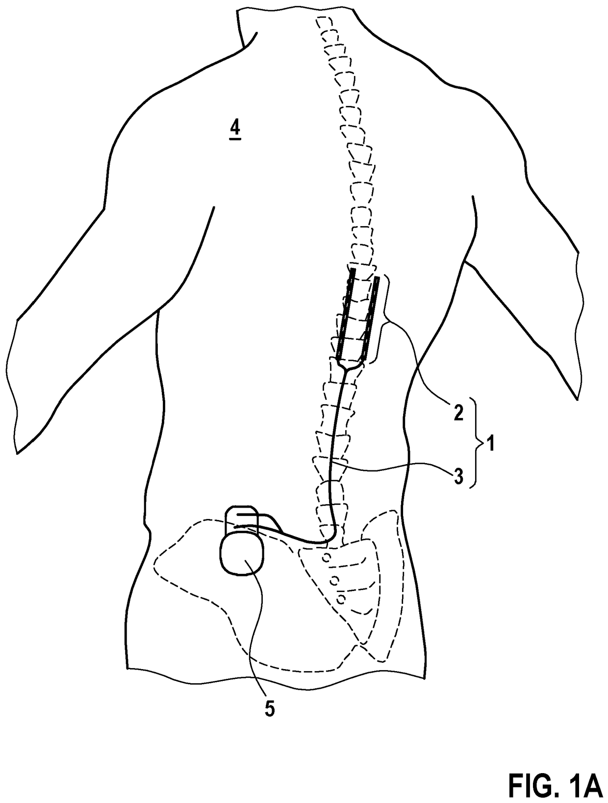 Figure 1A
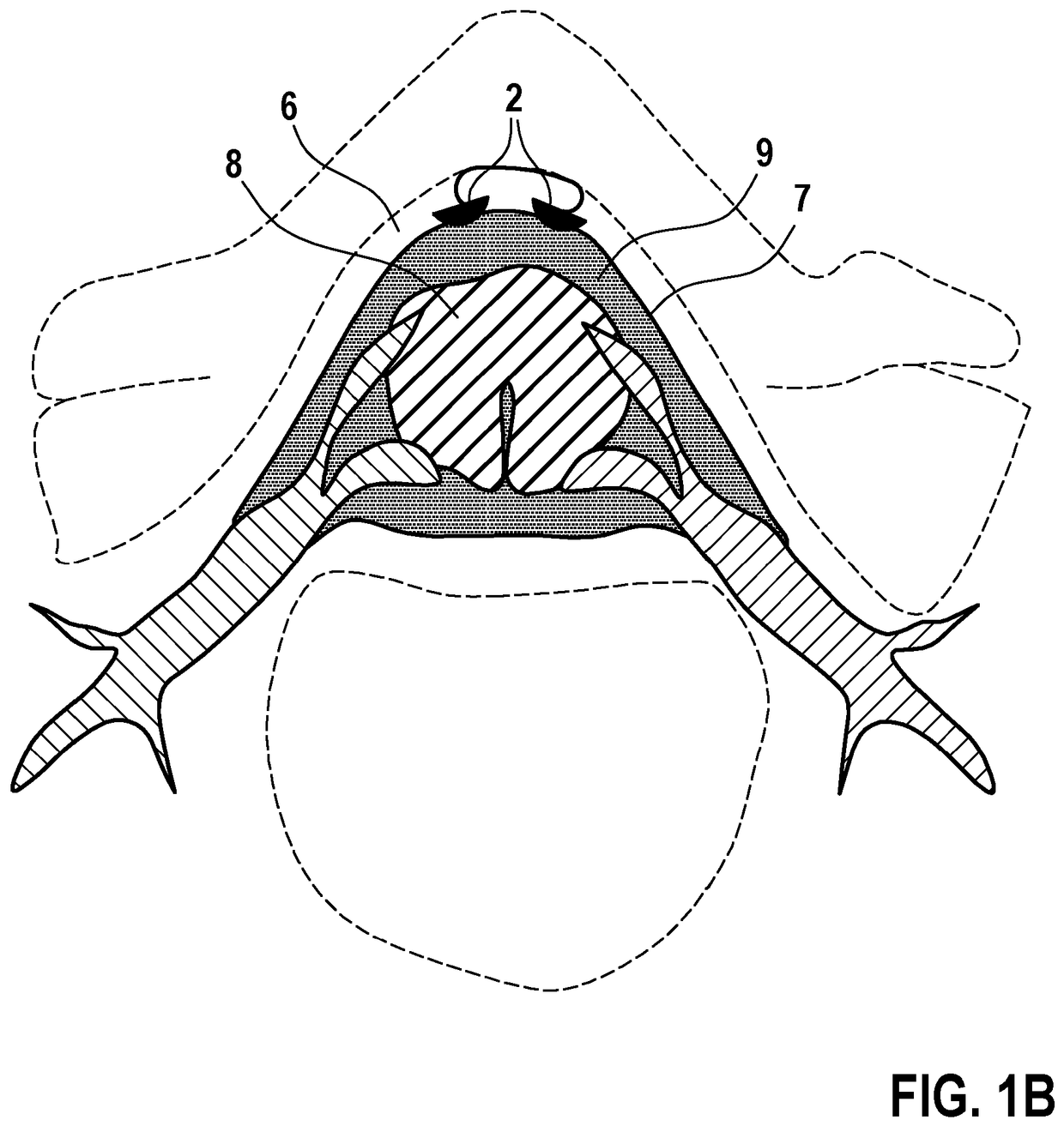 Figure 1B
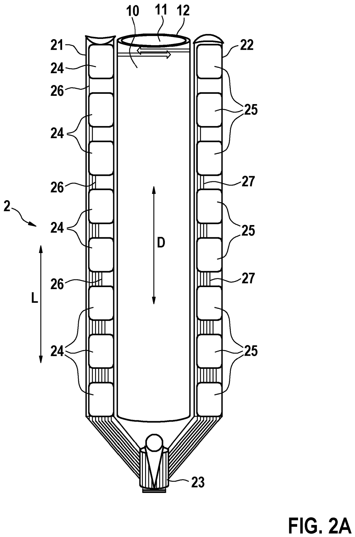 Figure 2A
AI summary
The invention relates to a paddle lead (1) for implantation in the epidural space through an insertion tool, the paddle lead (1) comprising a paddle structure (2) with a first paddle wing (21), a second paddle wing (22) and at least one resilient element (10, 14, 17, 18) connected with at least one of the first paddle wing (21) and the second paddle wing (22), wherein the at least one resilient member (10, 14, 17, 18) biases at least one of the first paddle wing (21) and the second paddle wing (22) to an expanded state. According to an aspect of the invention, the at least one resilient element (10, 14, 17, 18) has a longitudinal extension direction (D) that runs exclusively along the longitudinal extension direction (L) of the paddle structure (2) and in that the at least one resilient element (10, 14, 17, 18) has a wall (12, 15, 19, 20) that surrounds alone or with another part of the paddle structure (2) a hollow space (11, 16), wherein the hollow space (11, 16) also extends exclusively along the longitudinal extension direction (L) of the paddle structure (2).