
Partial discharge high-frequency current transformer and its preparation method
A high-frequency current and transformer technology, which is applied in the field of transformers, can solve problems such as unavoidable bump damage, unprotected terminals, and unsatisfactory anti-theft effects.
Patent Information
- Authority / Receiving Office
- CN · China
- Patent Type
- Patents(China)
- Current Assignee / Owner
- Publication Date
- 2015-12-02
Smart Images
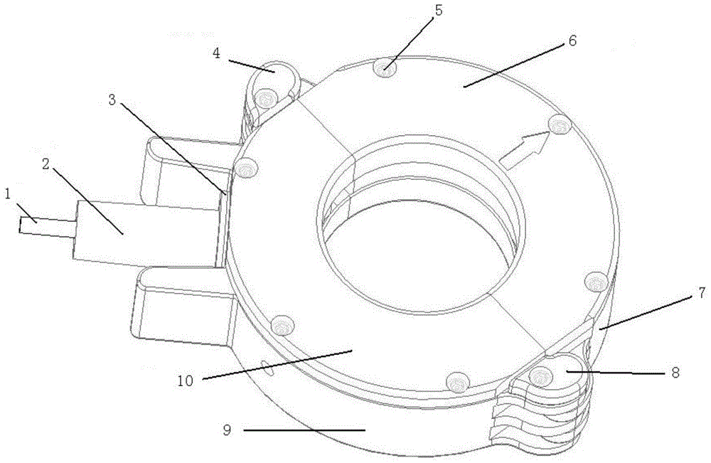
Figure 1 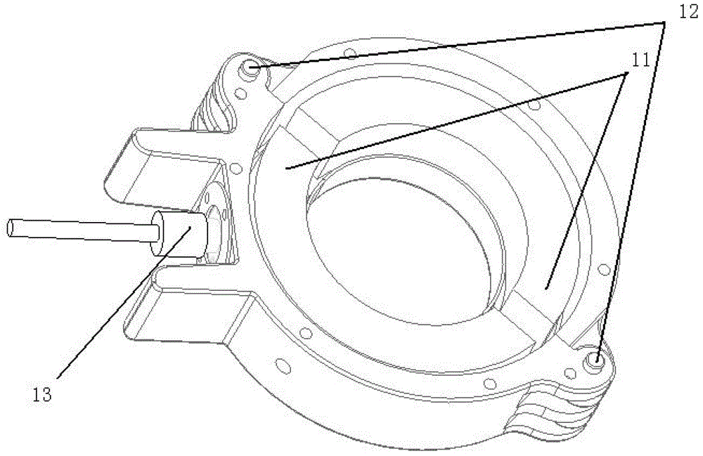
Figure 2 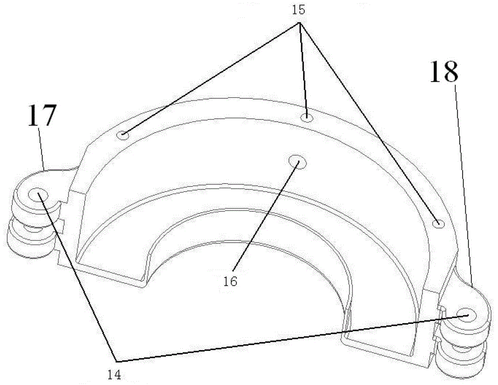
Figure 3
Abstract
Description
technical field
[0001] The invention relates to the technology in the field of transformers, in particular to a partial discharge high-frequency current transformer and a preparation method thereof. Background technique
[0002] Traditional current transformers mostly use hinges and buckles to meet their portability and installation requirements, but the anti-theft effect is not ideal, and the hinges and buckles are easily corroded and damaged; in addition, the terminal part of the traditional current transformer has no Protection, it is inevitable that it will be bumped and damaged during use or transportation, which will affect the function of the transformer. This patent is based on solving the disadvantages of this industry, and on the basis of portability and anti-corrosion, it has the function of anti-theft and the protection function of terminal blocks. Contents of the invention
[0003] The object of the present invention is to solve the above-mentioned problems, ...
Examples
Embodiment Construction
[0025] The present invention will be further described below in conjunction with the accompanying drawings and embodiments.
[0026] Such as Figure 1-4 As shown, a partial discharge high-frequency current transformer includes two semicircular magnetic cores 11 that can be spliced into a ring, and each of the semicircular magnetic cores 11 is installed in the magnetic core slot I7 and the magnetic core slot respectively. In the II9, the upper surface of the magnetic core groove I7 and the magnetic core groove II9 is respectively provided with a thin shell I6 and a thin shell II10, and the periphery of the upper surface of the magnetic core groove I7 and the magnetic core groove II9 is provided with a thin shell I6 There are several anti-theft screw installation holes 15 at intervals corresponding to the periphery of the thin case II10, through which the screws 5 are installed in the anti-theft screw installation holes 15 to realize that the thin case I6 and the thin case...