
Energy-saving self-excitation type retarding device
A retarder, self-excited technology, applied in the field of energy-saving self-excited retarder, can solve the problems of slow braking response, great influence of braking force, not considering the conversion of vehicle kinetic energy into electric energy, etc.
Patent Information
- Authority / Receiving Office
- CN · China
- Patent Type
- Patents(China)
- Current Assignee / Owner
- Publication Date
- 2015-06-10
Smart Images
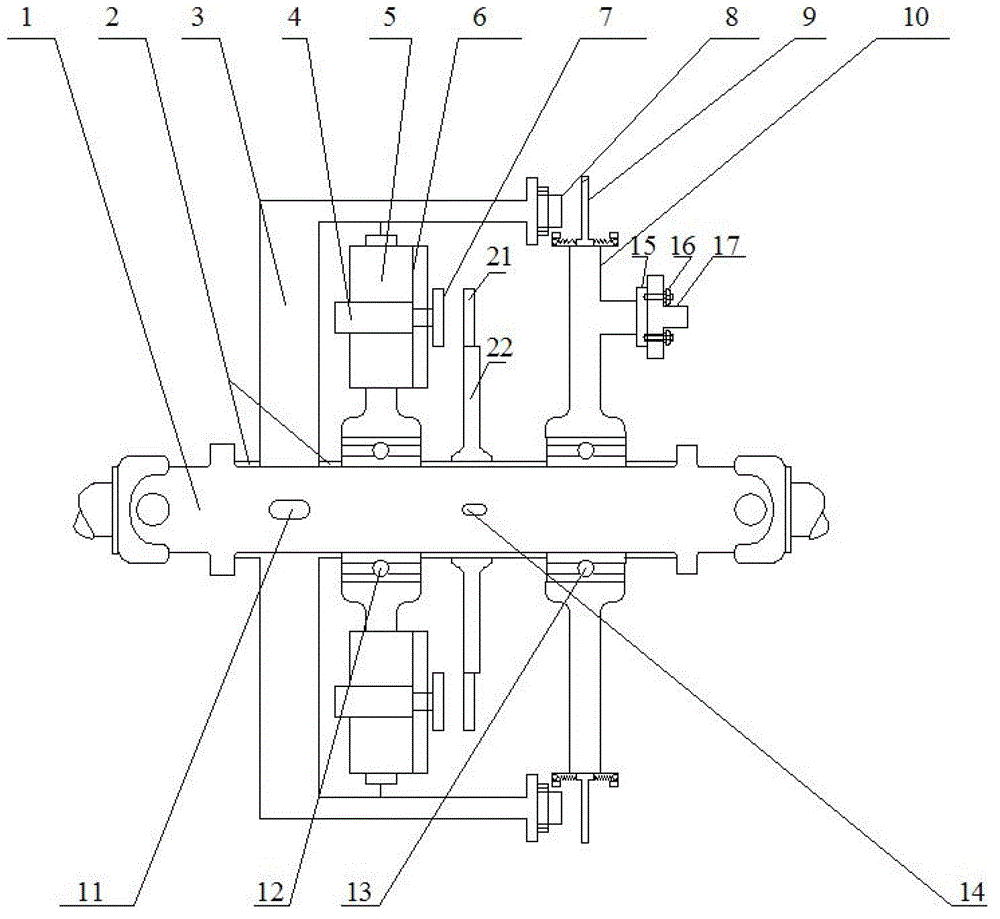
Figure 1 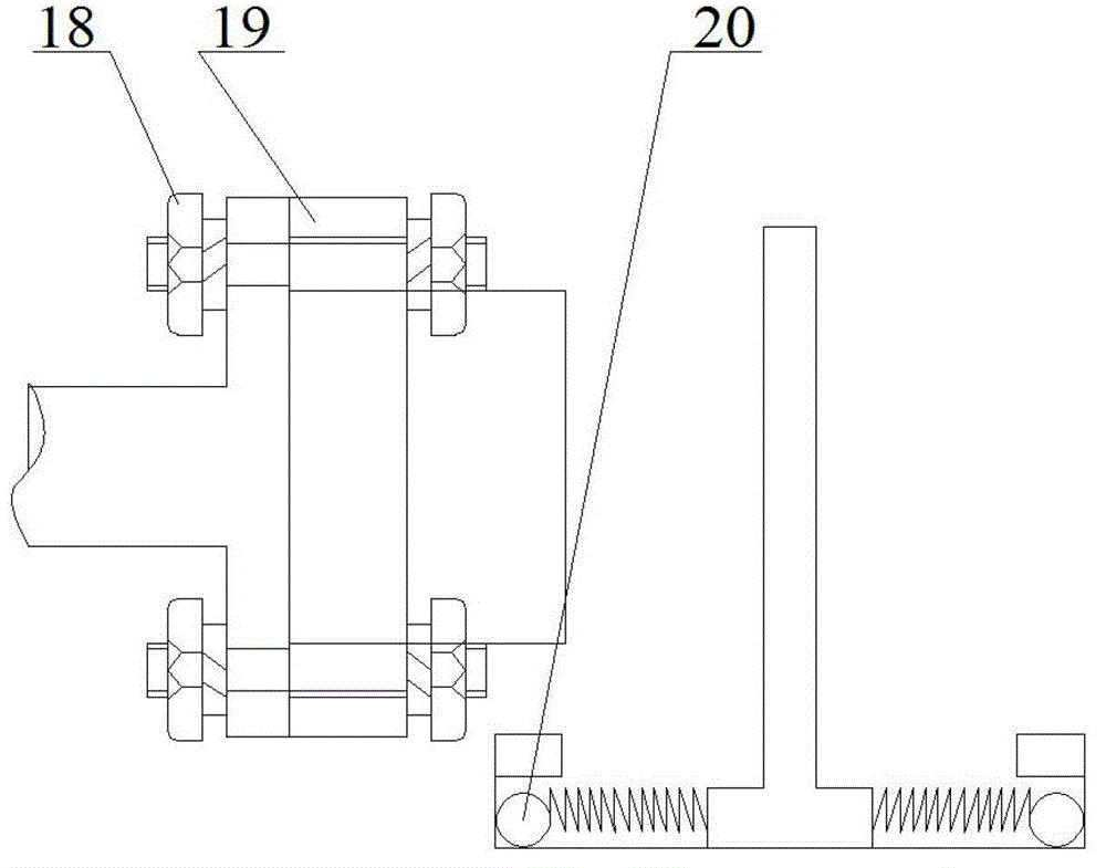
Figure 2
Abstract
Description
technical field
[0001] The invention belongs to the field of self-excited retarders, in particular to an energy-saving self-excited retarder. Background technique
[0002] As people pay more and more attention to the energy saving, environmental protection and driving safety of automobiles, how to better improve the energy saving and emission reduction effect and safety of vehicles has become the relentless goal pursued by more manufacturers. In terms of vehicle braking and energy saving, traditional mechanical friction brakes rely on frequent or long-term mechanical friction to brake. During the friction braking process, not only a large amount of toxic dust is generated, but also brake drums (discs) and friction plates are damaged. (Brake lining) is overheated, causes braking efficiency to decline even brake failure, and this kind of braking system all needs to be further improved in terms of energy saving, environmental protection and safe driving performance. The instal...
Examples
Embodiment Construction
[0011] Such as figure 1 As shown in and, the energy-saving self-excited retarder of the present invention comprises a self-excited retarder, an automobile transmission shaft 1 and a generator shaft 17, and the self-excited retarder is mainly composed of a retarder rotor disc 3, a retarder iron core 4 and the retarder coil 5; the retarder rotor disc 3, the rolling bearing 12 and the rolling bearing 2 13 are all supported on the automobile transmission shaft 1, and the retarder rotor disc 3 is connected with the transmission shaft 1 through the flat key 11, and the thrust The washer 2 is tightly fitted on the transmission shaft 1 to prevent the retarder rotor disk 3 from moving axially; the retarder coil support 6 supports the retarder coil 5, and the rolling bearing 12 supports the retarder coil support 6 and the electromagnetic clutch The coil moving plate 7, the rolling bearing 2 13 support the generator shaft connector support frame 10; the automobile drive shaft 1 is in the...