
A control device for a suspension train
A control device and technology for suspended trains, applied in the field of rail transit, can solve problems such as failure to meet the protection level and service life, failure to meet the control requirements of suspended trains, difficulty in replacing fans 02 and large quantity, etc., to achieve convenient control and reduce signal conversion parts, weight reduction effect
Patent Information
- Authority / Receiving Office
- CN · China
- Patent Type
- Patents(China)
- Current Assignee / Owner
- Publication Date
- 2015-10-21
Smart Images
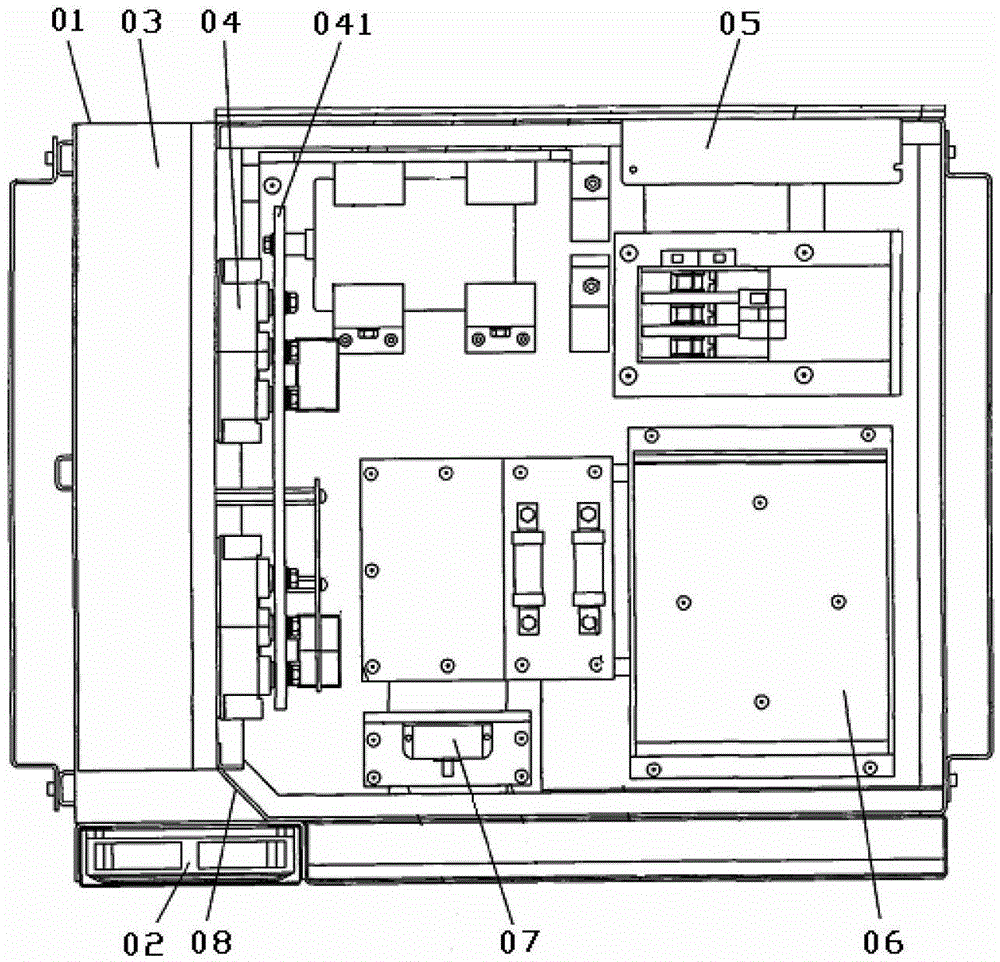
Figure 1 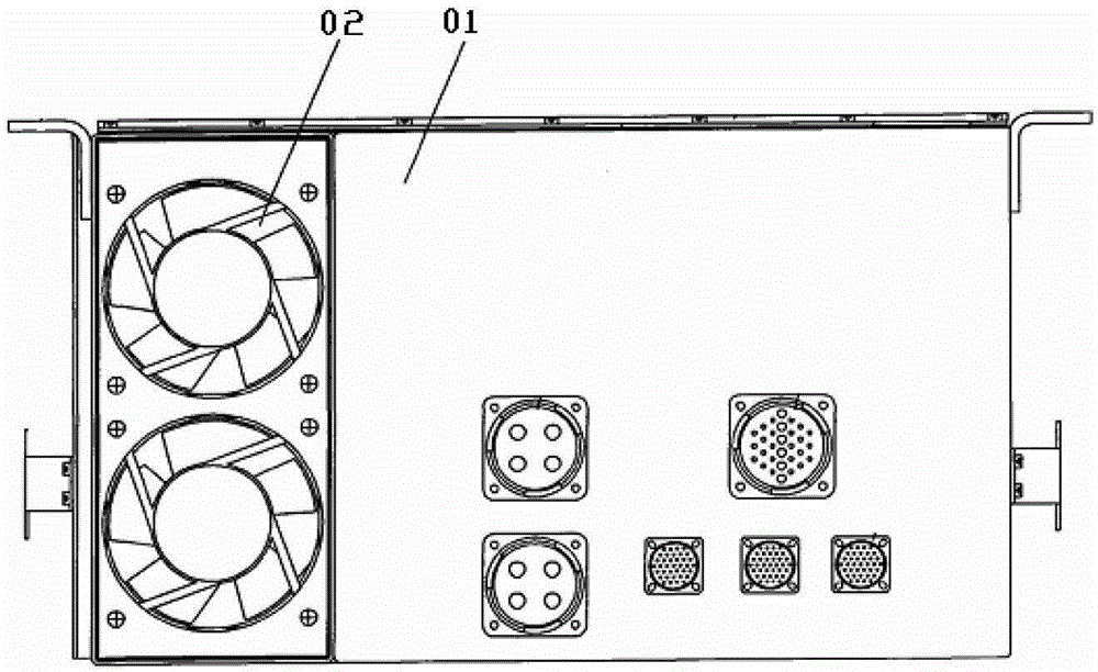
Figure 2 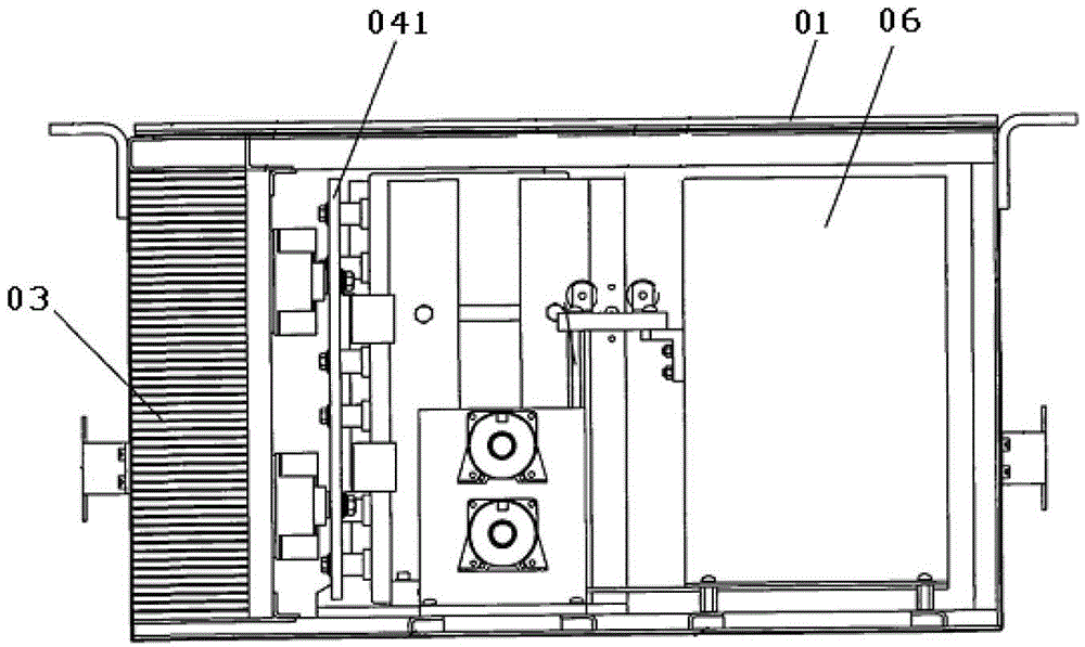
Figure 3
Abstract
Description
technical field
[0001] The invention relates to the technical field of rail transit, in particular to a control device for a suspension train. Background technique
[0002] In the prior art, the operation of the maglev train is controlled by a levitation controller. The levitation processor in the levitation controller calculates appropriate control commands based on the levitation gap measured by the levitation sensor, the vertical acceleration of the electromagnet, and the current data passing through the electromagnet, and transmits them to the levitation chopper. The command adjusts the electromagnetic force between the electromagnet and the rail, thereby adjusting the suspension gap and realizing the stable suspension of the train.
[0003] Due to the large inductance of the levitation electromagnet, when the current changes rapidly, the electromagnet will generate a high counter electromotive force, and the levitation chopper must bear high voltage and current. Under...
Examples
Embodiment Construction
[0027] The core of the present invention is to provide a control device for the train boundary, which can realize the detection of the train boundary in the running state, and has high detection accuracy and efficiency.
[0028] In order to enable those skilled in the art to better understand the solution of the present invention, the present invention will be further described in detail below in conjunction with the accompanying drawings and specific embodiments.
[0029] Please refer to Figure 4 with Figure 5 , Figure 4 It is a schematic diagram of the bottom view structure of the control device provided by the present invention in a specific embodiment; Figure 5 for Figure 4 A sectional view of the control unit shown along section line B-B.
[0030] In a specific implementation manner, the control device of the present invention includes a box body 1 and a power device 2 built in the box body 1. The power device 2 may be an IGBT (Insulated Gate Bipolar Transistor, ...