
Vibration attenuator for car seat back with adjustable vibration absorption frequency
A car seat and vibration attenuation technology, which is applied to vehicle seats, seat frames, vehicle parts, etc., to achieve the effects of improving dynamic comfort, simple structure and assembly process, and low cost
Patent Information
- Authority / Receiving Office
- CN · China
- Patent Type
- Patents(China)
- Current Assignee / Owner
- Publication Date
- 2017-03-29
Smart Images
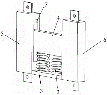
Figure 1 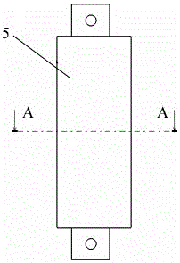
Figure 2 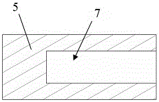
Figure 3
Abstract
Description
technical field
[0001] The invention relates to an accessory device of an automobile body, in particular to an automobile seat back vibration attenuator with adjustable vibration-absorbing frequency. Background technique
[0002] The car seat often produces strong vibration during driving. The dynamic comfort of the car seat refers to the comfort experienced by the seat after the vibration is transmitted to the human body through the seat frame and seat cushion under the driving state. It is mainly related to the vibration characteristics. related. The most sensitive frequency range of the human body is: the vertical vibration is 4~8Hz, and the horizontal vibration is below 2Hz. How to reduce the vibration in this frequency range as much as possible is the main goal. In order to make the car seat have good dynamic comfort, the passive vibration isolation method is widely used at home and abroad to attenuate the harmful vibration of the seat. Because the passive control vibr...
Examples
Embodiment Construction
[0014] The present invention will be further described below in conjunction with the accompanying drawings.
[0015] Such as Figure 1~Figure 4 As shown, the car seat back vibration attenuator with adjustable vibration-absorbing frequency includes a horizontally arranged base plate 3, a vertically upward left mounting plate 5 is provided at the left end of the base plate, and a vertically upward left mounting plate 5 is provided at the right end of the base plate. The right mounting plate 6 is respectively provided with relative chute 7 on the inner side of the left mounting plate and the right mounting plate, and a mass block 4 is arranged laterally above the base plate 3, and the two ends of the mass block 4 respectively extend into the chute 7 of the left mounting plate and the right mounting plate; two compression springs 2 are arranged between the bottom plate 3 and the mass block 4, and the mass block 4 can slide up and down along the chute and drive the compression Spr...