
A multi-stage swirl combustor with double return flow
A combustion chamber and swirl technology, applied in the combustion chamber, continuous combustion chamber, combustion method, etc., can solve the problems of poor working performance of the combustion chamber, low utilization rate of oxidant, poor mixing performance, etc. The effect of burning out, increasing the temperature, reducing the burning intensity
Patent Information
- Authority / Receiving Office
- CN · China
- Patent Type
- Patents(China)
- Current Assignee / Owner
- Publication Date
- 2017-11-21
Smart Images
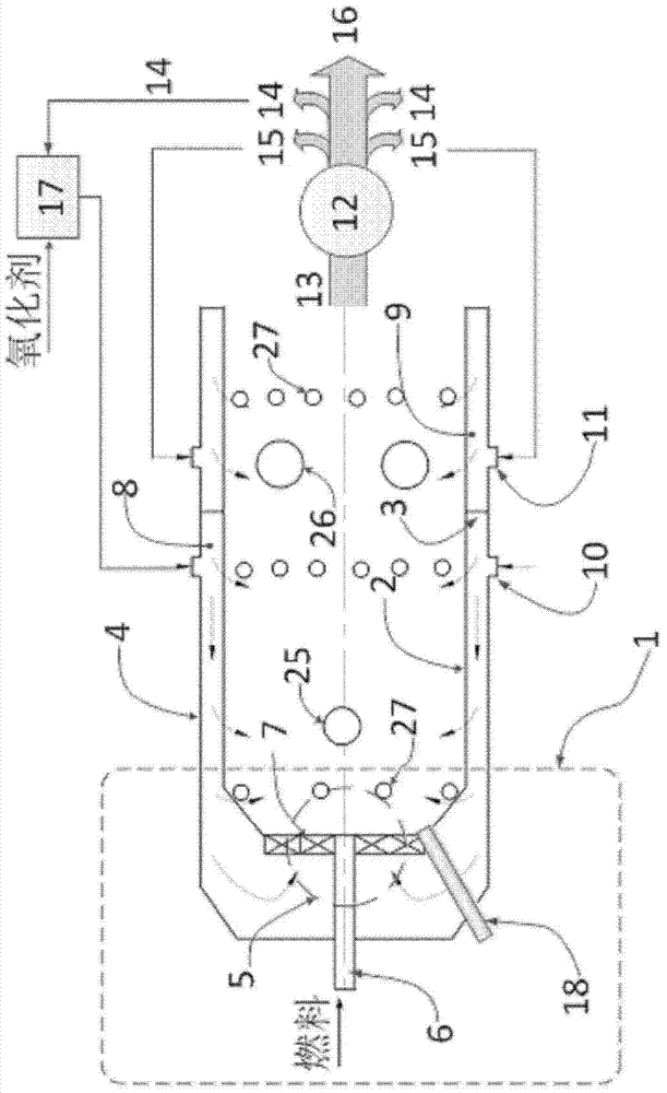
Figure 1 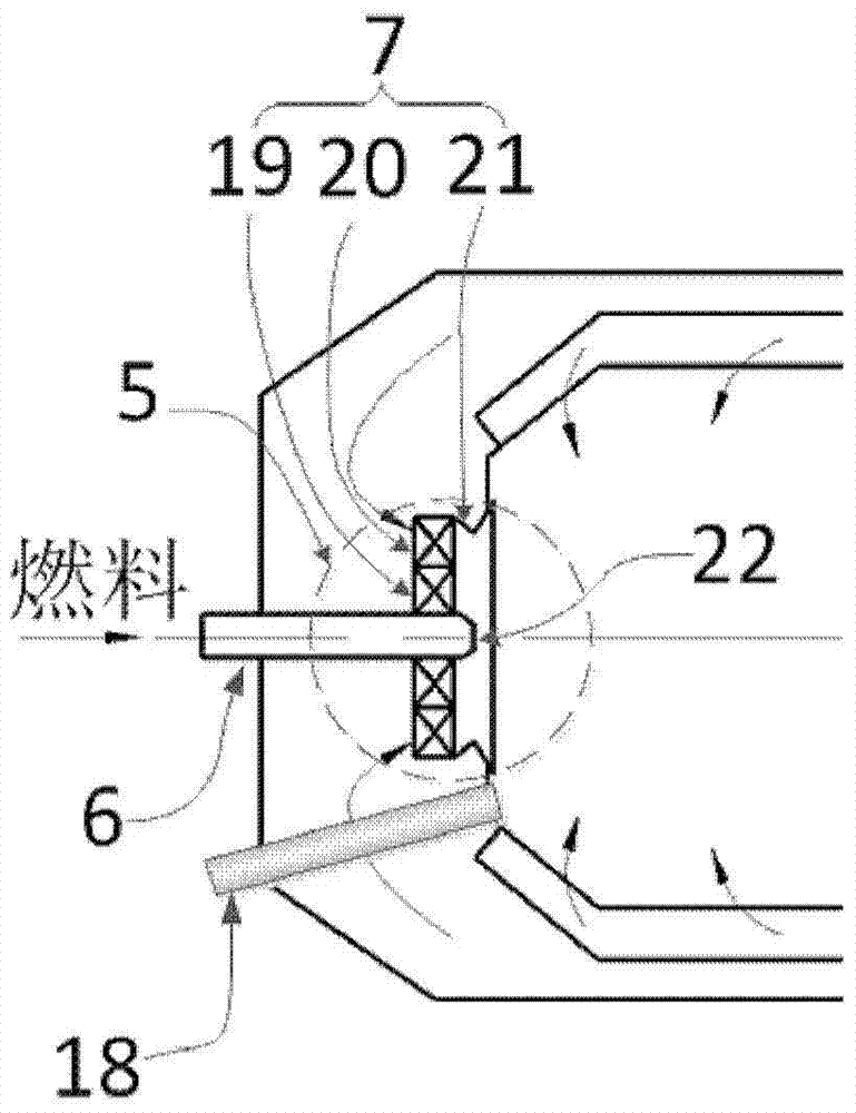
Figure 2 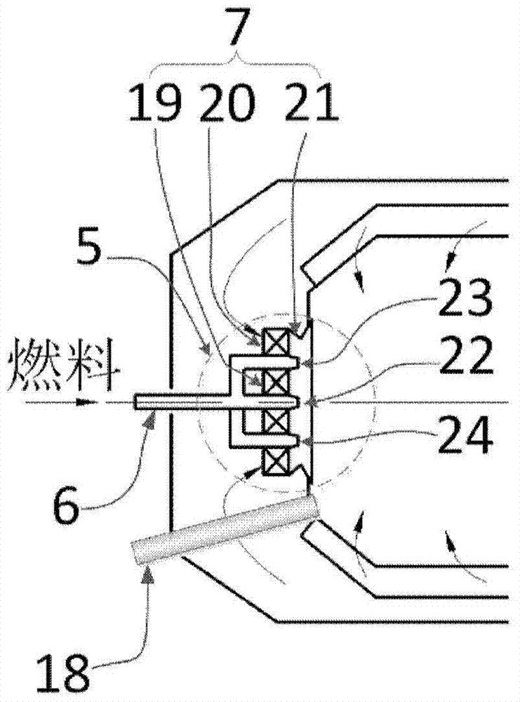
Figure 3
Abstract
Description
Technical field
[0001] The invention relates to the field of submarine power combustion, in particular to a multi-stage swirling combustion chamber with dual-path reflux. Background technique
[0002] The combustion head of the well-known submarine power combustion chamber is a single swirl burner, that is, a central fuel nozzle, and a single-stage swirler is provided on the outer ring of the fuel nozzle. The single-stage cyclone has the problems of uneven mixing and poor mixing performance in mixing fuel and oxidizer. The uneven mixing of fuel and oxidant leads to poor performance of the combustion chamber. In addition, the well-known type of combustion chamber adopts a radial double-ring cavity between the flame tube and the wall of the combustion chamber. In this form, flue gas flows in the inner ring cavity and oxidant flows in the outer ring cavity. Under this structure , There is no oxidant for afterburning in the combustion chamber, which leads to the problem of low comb...
Examples
Embodiment 1
[0033] See figure 1 with figure 2 , The structure of the first embodiment of the present invention is as follows:
[0034] The combustion chamber has a single tube structure, which is composed of a combustion head 1, a flame tube 2, a baffle 3, a combustion chamber wall 4, a heat exchanger 12 and a mixer 17. The dividing plate 3 divides the annular cavity between the flame tube 2 and the combustion chamber wall 4 into two upstream and downstream annular cavities. The upstream annular cavity of the dividing plate 3 is the first annular cavity 8, and the downstream annular cavity of the dividing plate 3 is The second ring cavity 9. The air inlet of the first ring cavity 8 is the first ring cavity interface 10, and the air inlet of the second ring cavity 9 is the second ring cavity interface 11. The combustion head 1 is composed of a combustor 5. The combustor 5 is composed of a fuel nozzle 6 arranged in the center and a swirler 7 in the outer ring. The fuel nozzle 6 is provided w...
Embodiment 2
[0037] See figure 1 with image 3 , Is a schematic structural diagram of the second embodiment of the present invention. The difference from the first embodiment is that the fuel nozzle 6 includes a plurality of nozzles, and the fuel nozzles and the swirler are arranged alternately. in image 3 Three fuel nozzles 22, 23, 24 are shown in the middle, and the fuel nozzles 22, 23, 24 and swirlers 19, 20 are arranged alternately. The rest is the same as in Example 1.