
warp knitting machine
A warp knitting machine and driving mechanism technology, applied in the field of warp knitting machines, can solve problems such as large structural space, and achieve the effect of saving structural elements, saving structural space and small quality
Patent Information
- Authority / Receiving Office
- CN · China
- Patent Type
- Patents(China)
- Current Assignee / Owner
- Publication Date
- 2019-05-14
Smart Images
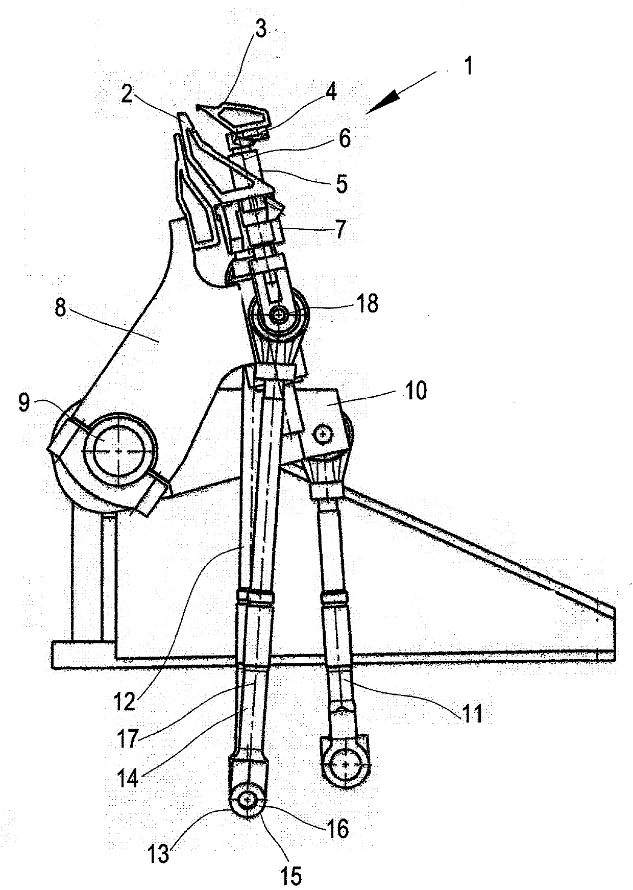
Figure 1
Abstract
Description
technical field
[0001] The invention relates to a warp knitting machine with a needle bar (Nadel barre) and a sliding bar (Schieber barre), the needle bar being actuated from the main shaft by means of a needle bar drive and the sliding bar being driven by a sliding bar drive Controlled by the spindle. Background technique
[0002] The needle bar carries a large number of knitting needles (Wirknadel), which are also called working needles. The knitting needle has a head which forms a hook with which the thread can be drawn through the previously formed loop during the loop forming process (Maschenbildungsvorgang). In order to prevent the hook from getting caught on the loop, a slide is provided for each needle, which covers the tip of the hook when the head of the needle is drawn through the previously formed loop.
[0003] The warp knitting machine also has further bars, which carry other loop forming tools, such as thread guide needles or the like. Both the pin bar and ...
Examples
Embodiment Construction
[0020] In the figure a part of a warp knitting machine 1 is shown with a needle bar 2 carrying a large number of knitting needles which are arranged one behind the other perpendicular to the plane of the drawing. The knitting needles are not shown in the drawings. Furthermore, the warp knitting machine 1 has a sliding bar 3 which carries a slide for each knitting needle. Sliders are also not shown.
[0021] The sliding bar 3 is fixed on a sliding bar carrier 4 which is guided in a linear guide 5 . The linear guide 5 has a plurality of linear guides which are arranged one behind the other perpendicular to the plane of the drawing. The linear guide 5 has a guide direction 6 .
[0022] The linear guide 5 is arranged in a pin bar carrier 7 which carries the pin bar 2 . The needle bar carrier 7 is in turn mounted movably on a carrier bar 8 . The carrier rod 8 is fixed on the shaft 9 in a rotationally fixed manner. The shaft 9 is driven in an oscillating movement by a tripper ...