
Methods and system for positioning an engine
A technology of engine and starter, applied in the direction of engine starting, engine components, combustion engine, etc., can solve the problems of increasing engine starting time, etc., and achieve the effect of reducing starting time, reducing electric energy consumption, and fast starting
Patent Information
- Authority / Receiving Office
- CN · China
- Patent Type
- Applications(China)
- Current Assignee / Owner
- Publication Date
- 2018-03-20
Smart Images
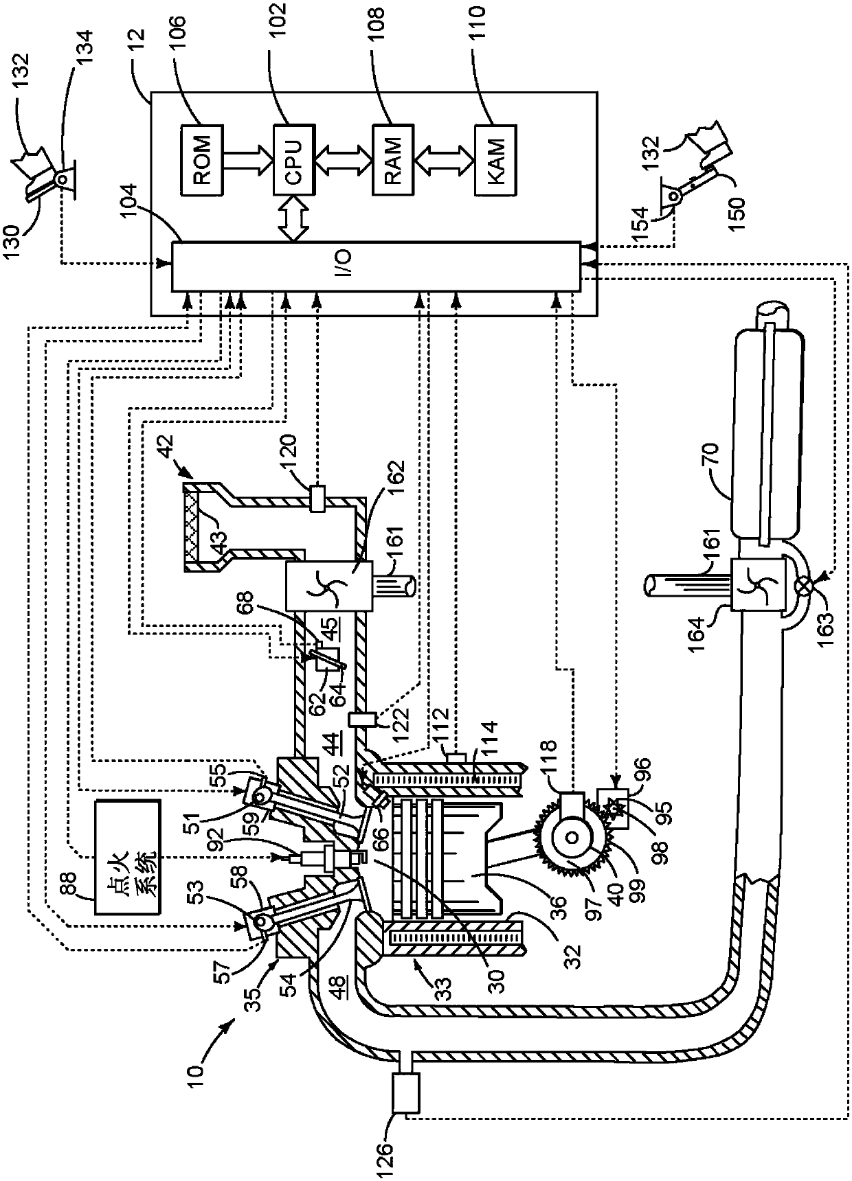
Figure 1 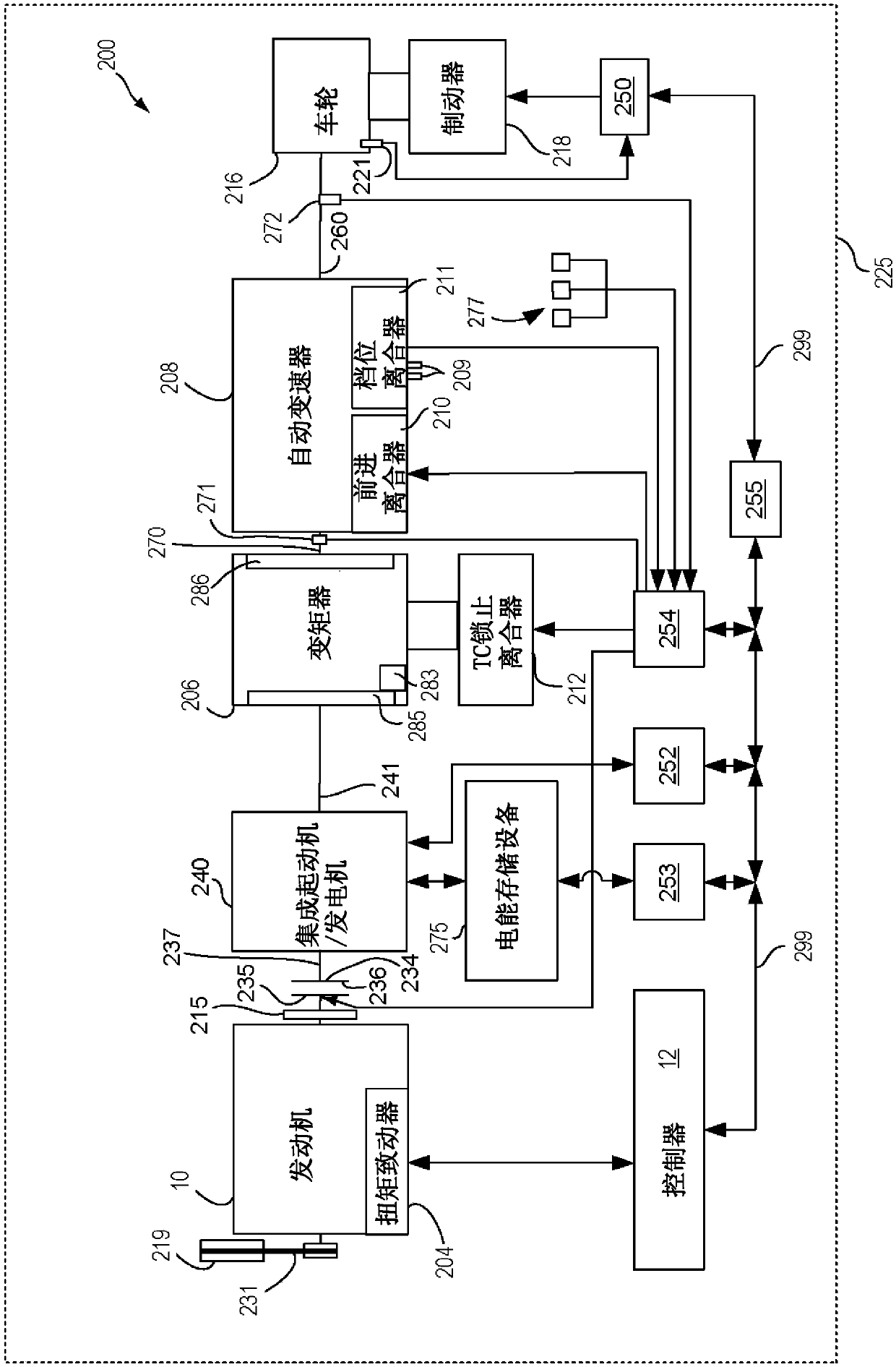
Figure 2 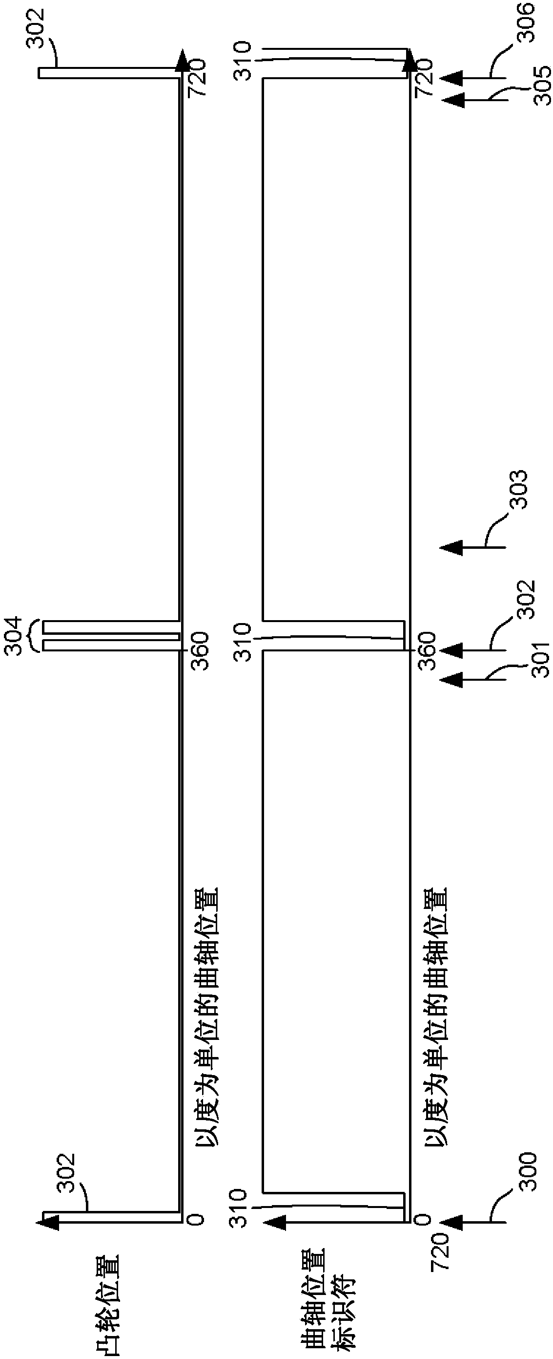
Figure 3
Abstract
Description
technical field
[0001] The present description relates to methods and systems for operating a hybrid powertrain including an engine and an electric machine for propelling a vehicle. The method and system are particularly useful for hybrid vehicles including engines and with integrated starter / generators and / or motor / generators. Background technique
[0002] When activating the vehicle, the internal combustion engine can be selectively stopped and started. When restarting the engine, it may be desirable to know the engine position so that fuel can be delivered to the engine cylinders in a timely manner so that the engine cylinders do not receive multiple fuel injections when only one fuel injection is desired. Further, by injecting fuel into engine cylinders at known engine positions, engine emissions may be reduced and engine start consistency may be provided. However, if the vehicle is deactivated, when the engine is stopped, it may not be ensured that the engine starts f...
Examples
Embodiment Construction
[0014] This description relates to controlling starting and stopping of a hybrid vehicle. Hybrid vehicles can include such figure 1 Internal combustion engine shown in . Internal combustion engines can be included in such figure 2 in the drivetrain or powertrain of a hybrid vehicle as shown in . available via image 3 The engine position signal shown establishes engine position. can be based on Figure 4-Figure 6 method of operating a hybrid powertrain. Figure 4-Figure 6 method can provide Figure 7 The sequence of vehicle operations shown in .
[0015] refer to figure 1 , an internal combustion engine 10 comprising a plurality of cylinders is controlled by an electronic engine controller 12, wherein figure 1 One of the cylinders is shown. Engine 10 includes cylinder head 35 and block 33 including combustion chamber 30 and cylinder walls 32 . Piston 36 is positioned therein and reciprocates via a connection to crankshaft 40 . Flywheel 97 and ring gear 99 are coup...