

High-life mute micro-switch
A technology of micro switch and longevity, applied in the direction of electric switches, electrical components, circuits, etc., can solve the problems of easy wear of the action reed, short life, and inability to apply to a quiet environment, so as to improve the overall life and reduce the impact force , the effect of increasing the thickness
Patent Information
- Authority / Receiving Office
- CN · China
- Patent Type
- Applications(China)
- Current Assignee / Owner
- Publication Date
- 2018-07-13
Smart Images
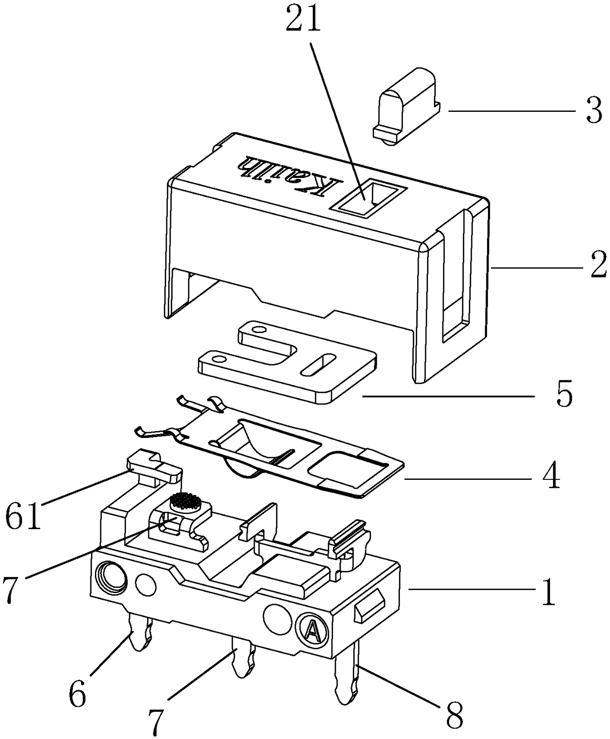
Figure 1 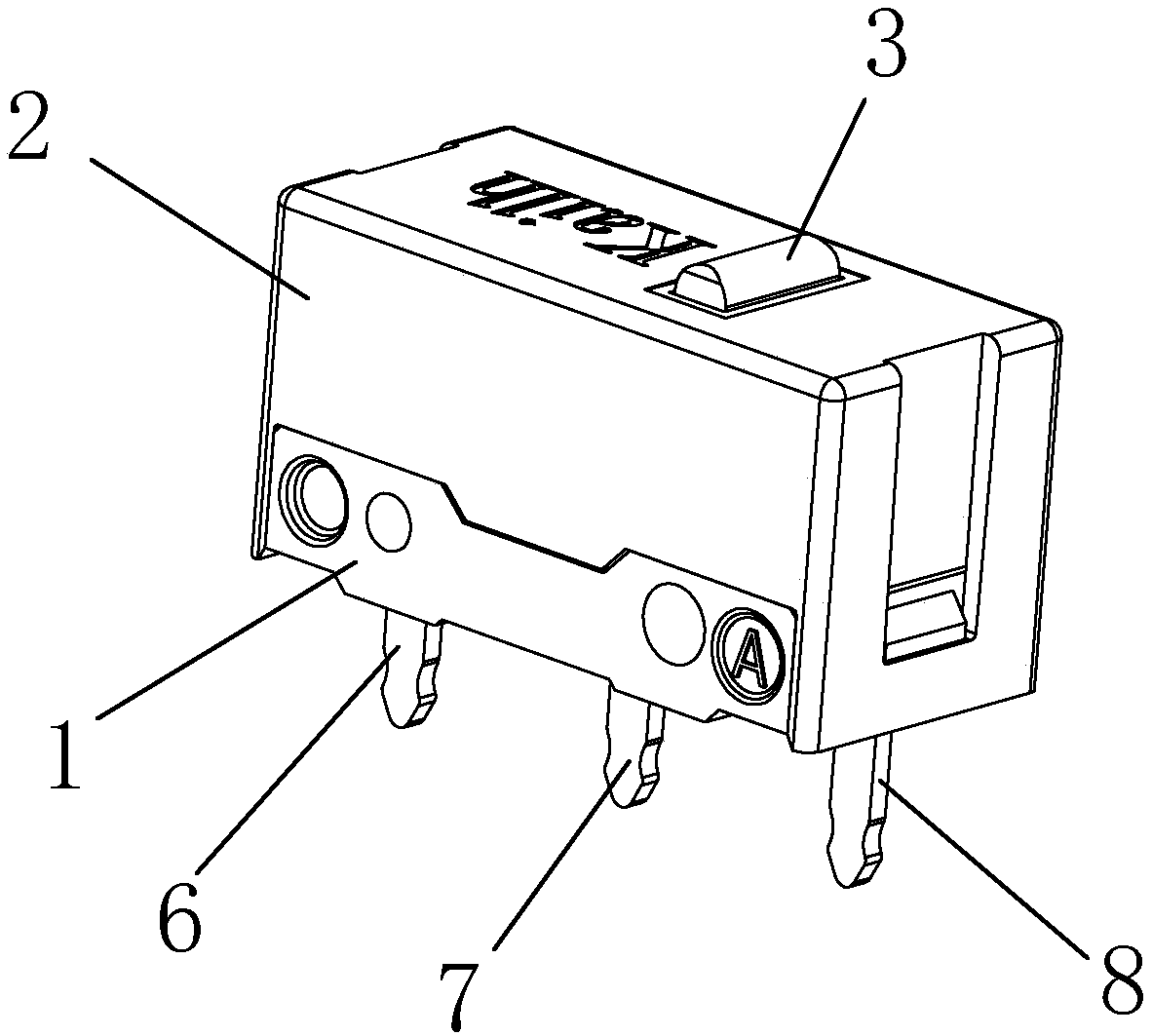
Figure 2 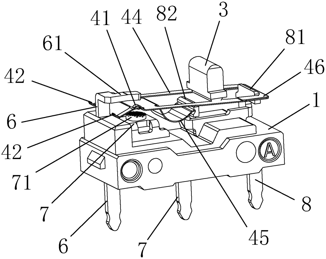
Figure 3
Abstract
Description
technical field
[0001] The invention relates to a micro switch, in particular to a high-life silent micro switch. Background technique
[0002] Micro switch is a commonly used switch mechanism. It is a contact mechanism with a small contact interval and a quick action mechanism that performs switching actions with a specified stroke and a specified force. It is widely used in industry, electronics, machinery, and governance. Gold, electricity and other fields.
[0003] The working principle of the existing micro switch is: the external mechanical force acts on the action reed through the transmission element (press pin, button, lever, roller, etc.), and when the action reed moves to the critical point, an instantaneous action is generated to make the action The moving contact at the end of the reed is quickly connected or disconnected from the static contact.
[0004] The existing micro switch usually adopts the method of setting the movable contact on the action reed. Bef...
Examples
Embodiment Construction
[0033] In order to further illustrate the technical means and functions adopted by the present invention to achieve the intended purpose, the specific implementation modes of the present invention will be described in detail below in conjunction with the accompanying drawings and preferred embodiments.
[0034] Please refer to Figure 1 to Figure 6 , the embodiment of the present invention provides a high-life mute micro switch, which includes a base 1 and a cover 2 that is closed on the base 1, and the cover 2 is closed on the base 1 to form an accommodating cavity. A guide core 3 is arranged in the accommodating cavity, and an upper opening 21 is opened on the cover 2 for the upper end of the guide core 3 to pass through. The micro switch of this embodiment also includes an elastic body 4 disposed in the accommodating cavity and below the guide core 3, and a flexible body 5 disposed on the lower end surface of the cover 2 and positioned above one end of the elastic body 4, w...