
Expressway police robot
A technology of highways and robots, applied in the direction of supporting machines, instruments, cameras, etc., can solve the problems of high cost, rising cost, fast speed, etc., and achieve the effect of improving the escape rate of personnel, reducing the accident rate, and improving emergency response capabilities
Patent Information
- Authority / Receiving Office
- CN · China
- Patent Type
- Applications(China)
- Current Assignee / Owner
- Publication Date
- 2018-11-27
- Estimated Expiration
- Not applicable · inactive patent
Smart Images
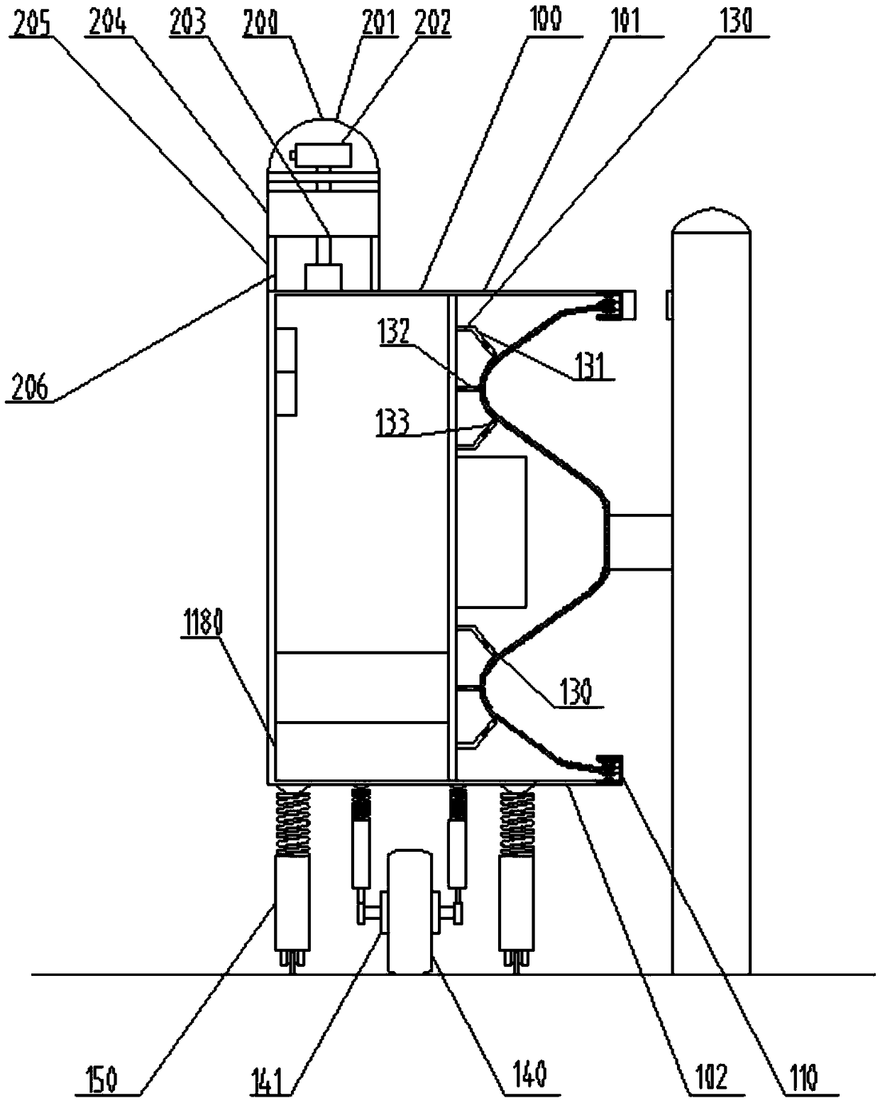
Figure 1 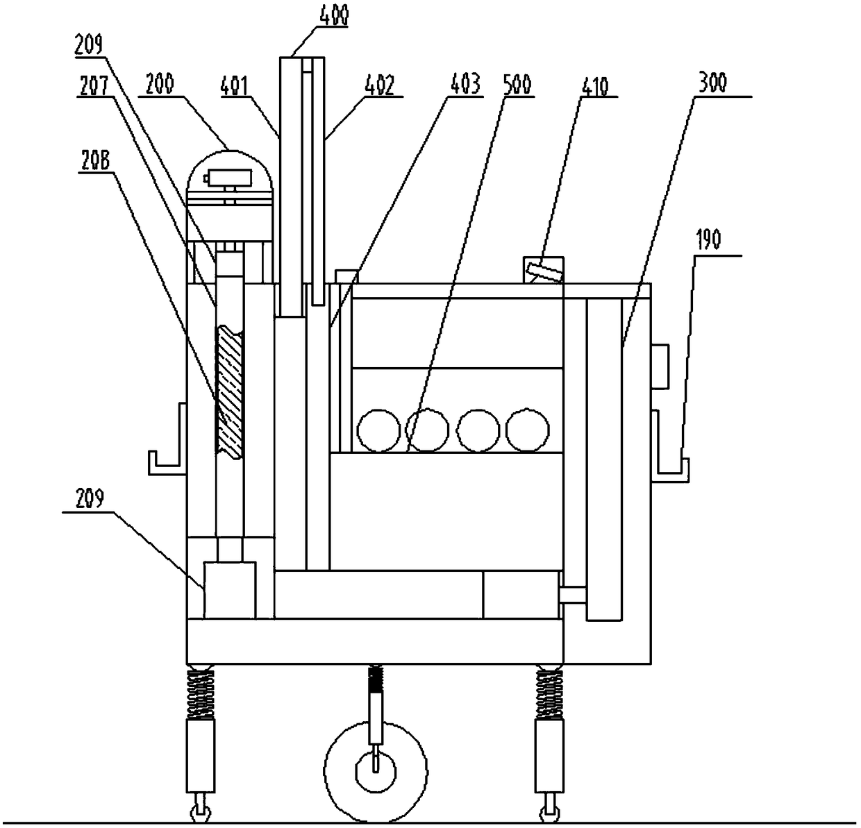
Figure 2 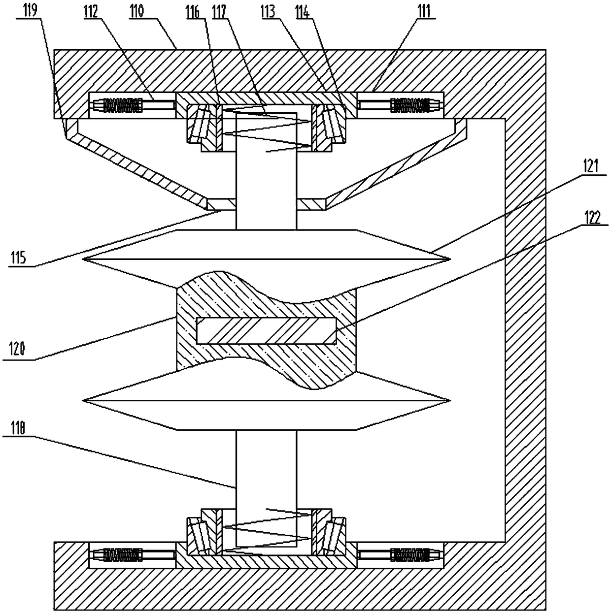
Figure 3
Abstract
Description
technical field
[0001] The invention relates to a police robot used on expressways. Background technique
[0002] Due to the long distance and fast speed of the expressway, the traffic police cannot monitor the whole process. They can only monitor the passing vehicles and the situation of the road section through fixed-installed cameras. Daily patrols can only be inspected by car, which is very inefficient and very costly. Because a car patrols a road section, it needs to go all the way, which is time-consuming, and the patrol is basically performed at a single point, that is, a car patrols a road section. The use of vehicles and the input of personnel will greatly increase the cost. Contents of the invention
[0003] The purpose of the present invention is to provide a highway police robot with high patrol efficiency and low cost.
[0004] In order to achieve the above object, the present invention includes a box body, the bottom surface of the box body is a plane, and...
Examples
Embodiment Construction
[0059] The invention will be described in detail below in conjunction with the accompanying drawings.
[0060] Such as Figures 1 to 4 Shown, a kind of expressway police robot comprises box body 100, and the bottom surface of box body 100 is plane, and its bottom surface is fixed not less than four auxiliary wheels 150, and auxiliary wheels 150 are evenly distributed around the bottom surface of box body 100, and auxiliary wheels A drive wheel 140 is fixed at the center of 150, and the travel motor 141 is fixed on the hub axis of the drive wheel 140,
[0061] The box body 100 fixes an upper positioning plate 101 and a lower positioning plate 102 extending parallel to the outside on one side of the axial direction of the driving wheel 140, and a plurality of fences are fixed on one side of the spare end of the upper positioning plate 101 and the lower positioning plate 101 for positioning. device 110;
[0062] Described fence positioning device 110 comprises a U-shaped box bo...