
Hotel special-purpose clothes drying device facilitating separation of clothes
A technology for hotels and clothes, which is applied in the field of special clothes-drying devices for hotels, which can solve problems such as inconvenience for occupants, no place to dry clothes, and nowhere to dry clothes, so as to prevent the room from getting wet
Patent Information
- Authority / Receiving Office
- CN · China
- Current Assignee / Owner
- Publication Date
- 2018-12-14
- Estimated Expiration
- Not applicable · inactive patent
Smart Images
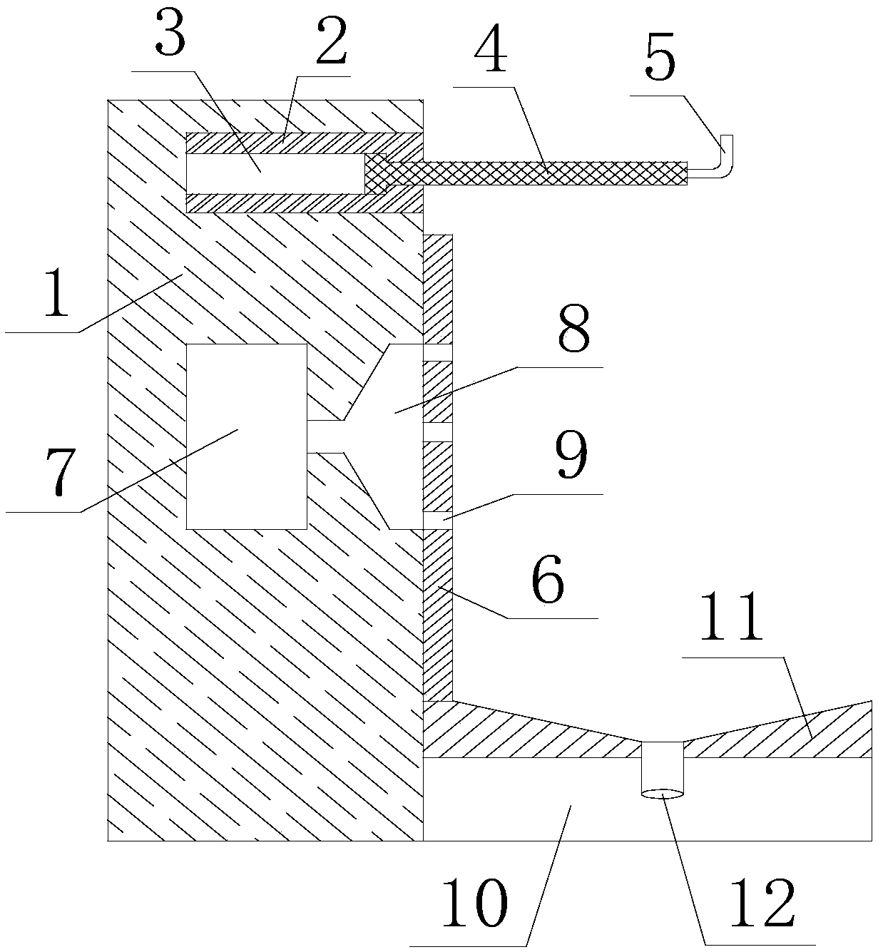
Figure 1 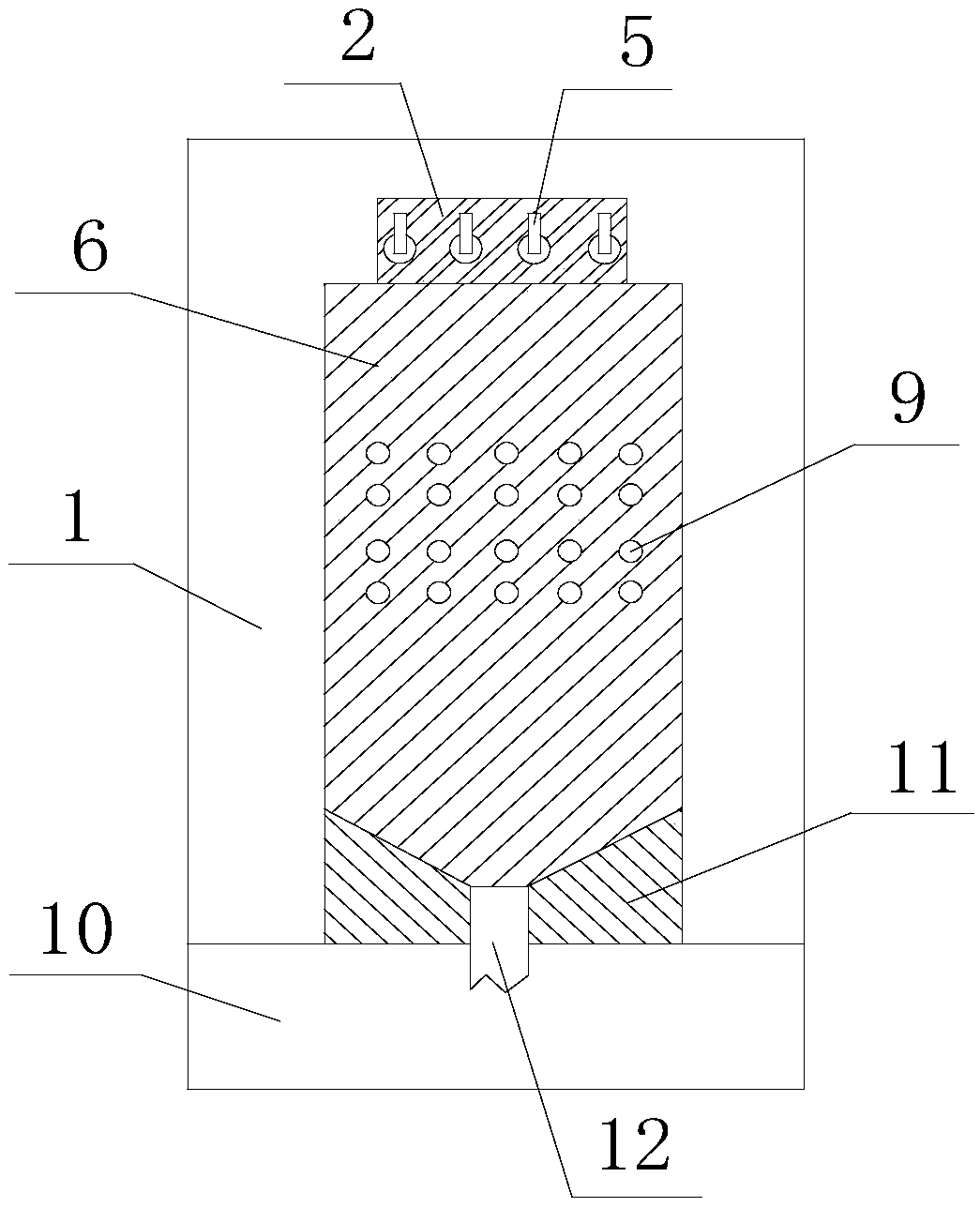
Figure 2 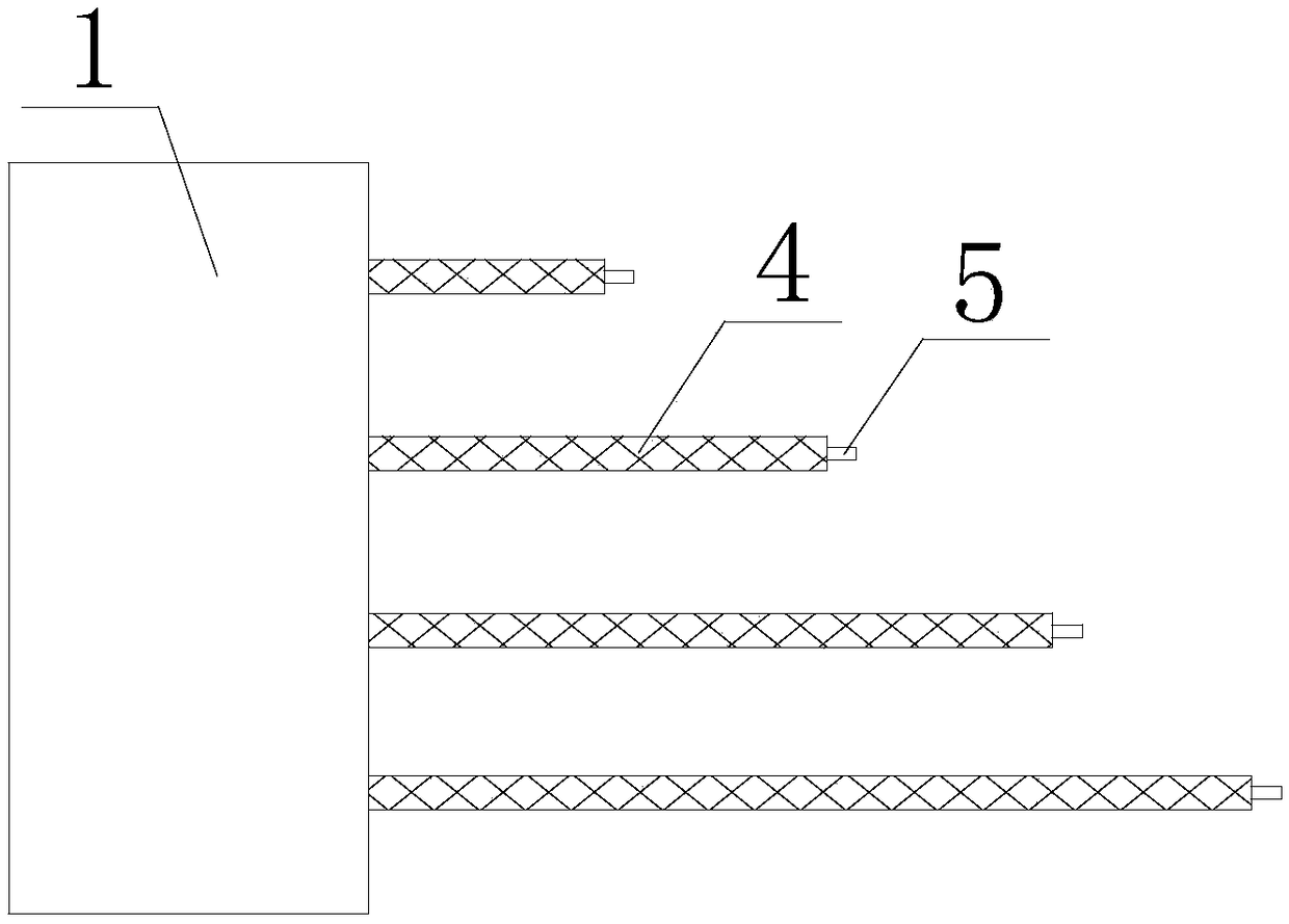
Figure 3
Abstract
Description
Technical field
[0001] The invention relates to hotel supplies, in particular to a hotel special clothes drying device which is convenient for clothes separation. Background technique
[0002] People live in business hotels when they are on a business trip. If they travel for a long time, they usually bring multiple sets of clothes to change and wash. Generally, hotels only have drying racks and no place to dry the clothes. Therefore, there is usually no laundry. The situation of air drying brings greater inconvenience to the occupants. Summary of the invention
[0003] In view of the shortcomings of the prior art, the present invention provides a hotel-specific clothes drying device that facilitates the separation of clothes. When applied, it can provide a place for occupants to dry clothes in a hotel room, and it can centrally process the water droplets from the clothes. Prevent the room from getting wet.
[0004] The present invention is realized through the following technical...
Examples
Example Embodiment
[0025] Example
[0026] A hotel-specific clothes drying device that facilitates the separation of clothes includes a wall 1, a storage piece 2 and a number of connecting rods 4. The storage piece 2 is arranged in the wall 1, and the storage piece 2 is provided with a number of sliding grooves 3, each sliding There are connecting rods 4 in the groove 3, and the connecting rods 4 extend out of the wall 1. All the connecting rods 4 are arranged in a row, and the lengths of the connecting rods 4 are successively reduced. The front end of each connecting rod 4 is provided The hook 5 is provided with a waterproof layer 6 on the surface of the wall 1 under the connecting rod 4, and a water collector 11 is provided on the floor 10 directly below the hook 5, and the water collector 11 is provided with a drain 12 and a drain 12 Connect with the drainage pipe in the room.
[0027] In specific implementation, the connecting rod 4 is pulled out from the storage member 2 through the sliding gro...