
A robot-based automatic nail feeding system and its working method
A working method and robot technology, applied in the field of aviation manufacturing, can solve the problems of low efficiency, high failure rate, slow nail feeding speed, etc., and achieve the effect of large working range, saving occupied area, and ensuring the discharging speed.
Patent Information
- Authority / Receiving Office
- CN · China
- Patent Type
- Patents(China)
- Current Assignee / Owner
- Publication Date
- 2019-07-09
Smart Images
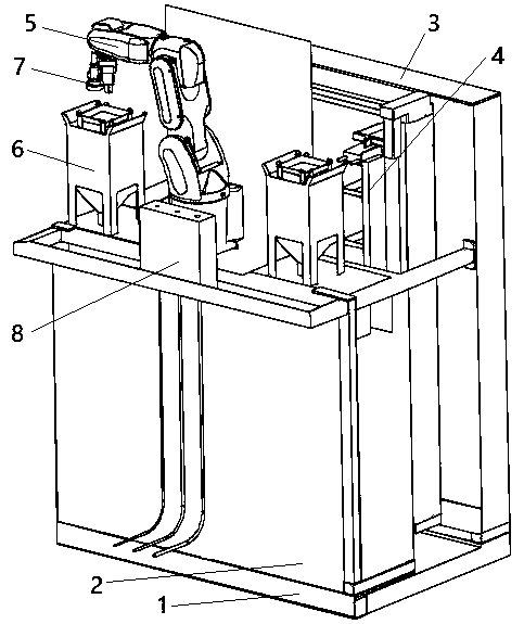
Figure 1 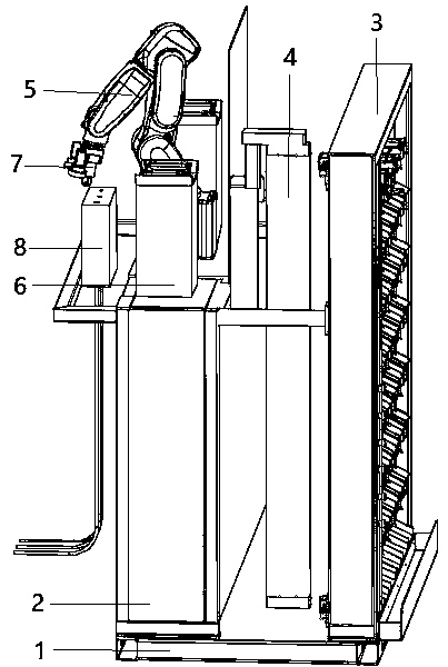
Figure 2 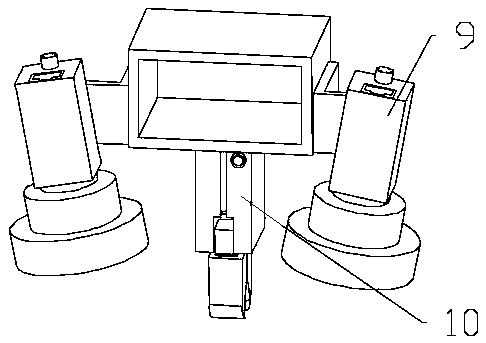
Figure 3
Abstract
Description
technical field
[0001] The invention relates to the field of aviation manufacturing, in particular to a robot-based automatic nail feeding system and a working method thereof. Background technique
[0002] With the development of my country's large passenger aircraft and new fighter jets, there are new requirements for aircraft manufacturing in terms of high quality, high efficiency, and long life. Traditional manual drilling and riveting has been difficult to meet the precision requirements in aircraft assembly. Therefore, the use of automatic drilling and riveting systems is a development trend in the field of aircraft assembly. Since the drilling and riveting efficiency of the automatic drilling and riveting system is high, an efficient automatic nail feeding system is required to deliver various specifications of rivets to the end of the drilling and riveting.
[0003] The current automatic nail feeding system mostly uses a vibrating plate to feed nails directly, or us...
Examples
Embodiment Construction
[0043] In order to make the object, technical solution and advantages of the present invention clearer, the technical solution of the present invention will be further described in detail below in conjunction with the accompanying drawings and specific embodiments.
[0044] Such as figure 1 , figure 2 As shown, a robot-based automatic nail feeding system includes a base 1, a control cabinet 2 is installed on one side of the base 1, and a rivet storage rack 3 is installed on the other side;
[0045] A discharge device 4 is fixedly installed between the control cabinet 2 and the rivet storage rack 3;
[0046] An industrial robot 5 and a plurality of grasping stations 6 are fixedly installed on the control cabinet 2, and the plurality of grasping stations 6 are distributed on both sides of the industrial robot 5;
[0047] A flange is provided on the industrial robot 5, and a visual grasping terminal 7 is installed on the flange;
[0048] Industrial robot 5 is also provided wi...