
Hybrid control synchronous valve
A technology of hybrid control and synchronizing valve, applied in control valve, valve detail, multi-port valve and other directions, can solve the problem of low synchronization accuracy of synchronization valve, and achieve the effect of reducing outflow, improving work efficiency and improving synchronization accuracy.
Patent Information
- Authority / Receiving Office
- CN · China
- Patent Type
- Applications(China)
- Current Assignee / Owner
- Publication Date
- 2019-04-23
Smart Images
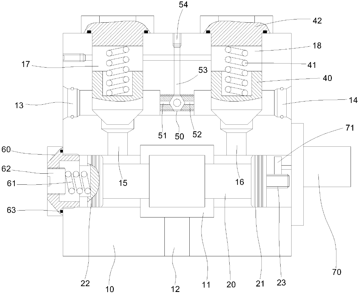
Figure 1
Abstract
Description
technical field
[0001] The invention relates to the technical field of synchronous valves, in particular to a mixing control synchronous valve. Background technique
[0002] The synchronous valve is used to ensure that two or more actuators (hydraulic cylinders or hydraulic motors) can still obtain the same or a certain proportion of flow when they are subjected to different loads, so that the same displacement or the same displacement between the actuators A hydraulic component that moves at high speed, the synchronous valve is used to synchronize the lifting mechanism. In the use of the synchronous lifting mechanism, a hydraulic valve is basically used to control an actuator. During the lifting process, due to the difference in working resistance, the lifting of the pillars is not synchronized, which causes the speed to be out of sync and affects the movement accuracy. The typical structure of the traditional synchronous valve is the hook type and the reversing piston typ...
Examples
Embodiment
[0021] Please refer to figure 1 , a mixing control synchronous valve, including a valve body 10, the lower part of the valve body 10 is provided with an oil inlet chamber 11, the oil inlet chamber 11 is provided with a main valve core 20, and the valve body 10 is provided with an oil inlet port under the oil inlet chamber 11 12. On both sides of the upper part of the valve body 10, the left oil outlet 13 and the right oil outlet 14 are respectively connected. The oil chamber 11 is connected, and the valve body 10 is provided with a left oil chamber 17 above the left passage 15, and a right oil chamber 18 above the right passage 16;
[0022] The left oil chamber 17 and the right oil chamber 18 are provided with an oil outlet valve core 40; the left and right ends of the main valve core 20 are respectively provided with a left piston 22 and a right piston 21; There is a control part 23 at the right end of the main valve core 20, and the drive unit 70 makes the main valve core 2...