
Door locking device
A technology of locking device and door opening, which is applied in the directions of fastening devices, transportation and packaging, and building fastening devices of wing sashes. Quick and easy effects
Patent Information
- Authority / Receiving Office
- CN · China
- Patent Type
- Applications(China)
- Current Assignee / Owner
- Publication Date
- 2021-07-09
Smart Images
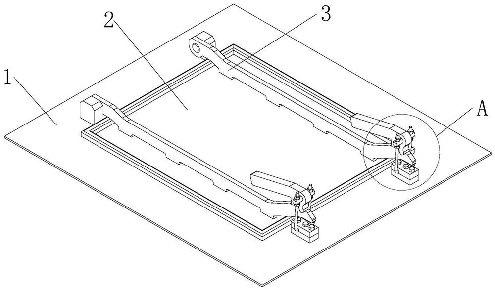
Figure 1 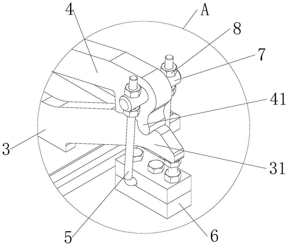
Figure 2 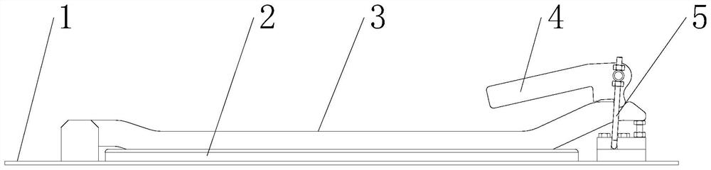
Figure 3
Abstract
Description
technical field
[0001] The invention relates to a locking device for a door, belonging to the technical field of auxiliary devices for mixing equipment. Background technique
[0002] Mixing equipment is a mechanical device that uses mechanical force and gravity to uniformly mix two or more materials. During the mixing process, the contact surface area of the material can also be increased to promote chemical reactions and accelerate physical changes. Mixing equipment usually has cleaning doors, inspection doors, etc. to facilitate cleaning or maintenance inside the equipment. The traditional door switch is locked. Composed of swing bolts and star nuts, the purpose of opening and closing the door is achieved through the connection between star nuts and swing bolts. However, this locking device is inconvenient to operate and needs to be disassembled by continuously turning the star nuts. When the time is closed, the connection between the star nut and the swing bolt is easy...
Examples
Embodiment Construction
[0020] In order to easily understand the technical means, creative features, goals and effects of the present invention, the present invention will be further described below in conjunction with specific illustrations.
[0021] Such as Figure 1-4 As shown, a locking device for a door includes a device body 1, a door opening is provided on the device body 1, two connecting rods 3 arranged in parallel are hinged on the device body 1, and the bottoms of the two connecting rods 3 are jointly fixedly connected with a For the airtight door 2 that matches the door opening, the ends of the two connecting rods 3 are provided with matching compression handles 4, and the compression handles 4 are connected to a U-shaped rod 5 through a pin shaft 7, and the U-shaped rod 5 passes through the fixing seat 6 It is rotatably connected with the device body 1.
[0022] The U-shaped bar 5 is provided with a pressing force adjusting mechanism, and the pressing force adjusting mechanism includes ...