
Equipoising support apparatus
Patent Information
- Authority / Receiving Office
- US · United States
- Current Assignee / Owner
- Publication Date
- 2006-11-23
Smart Images
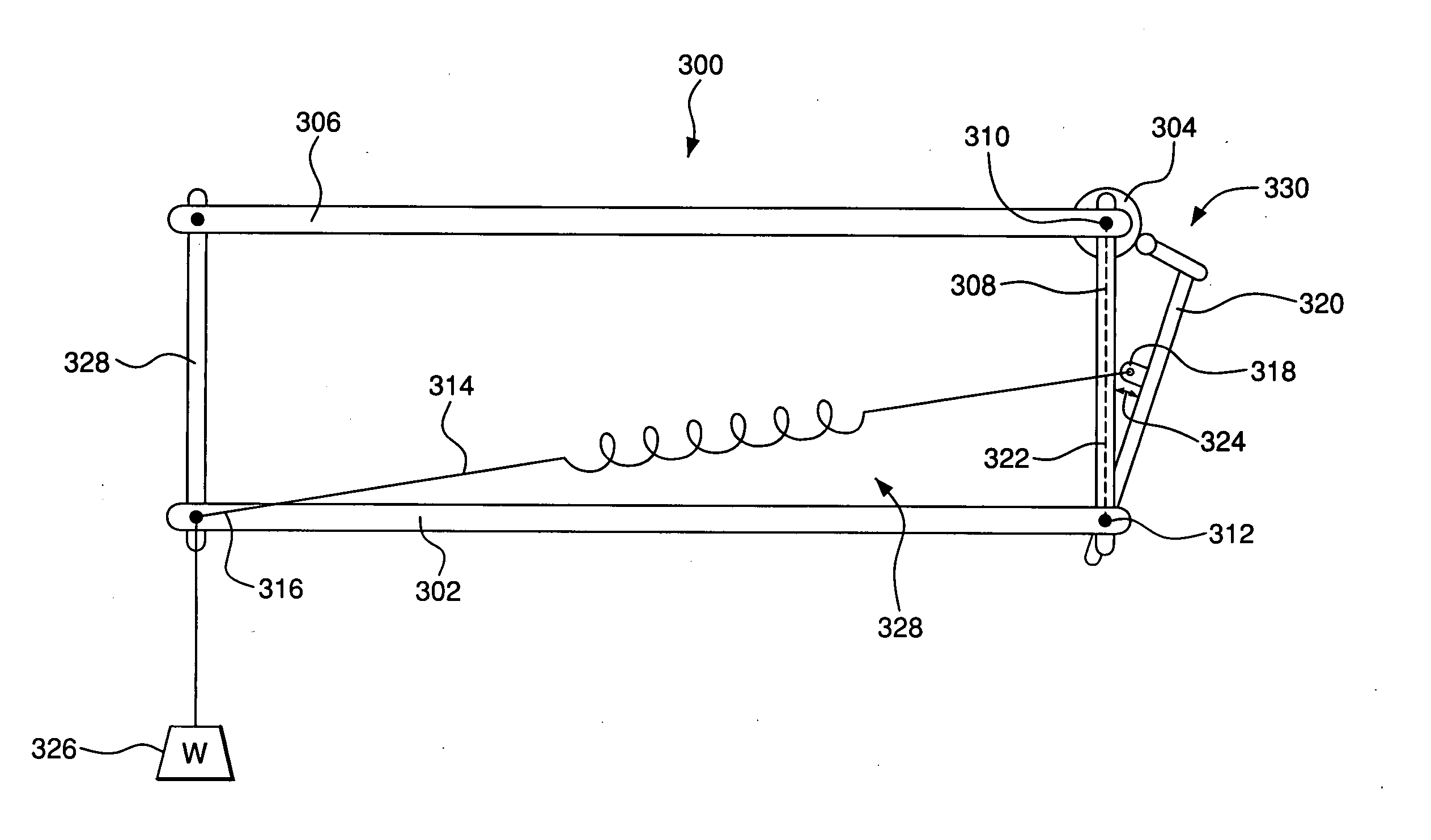
Figure 1 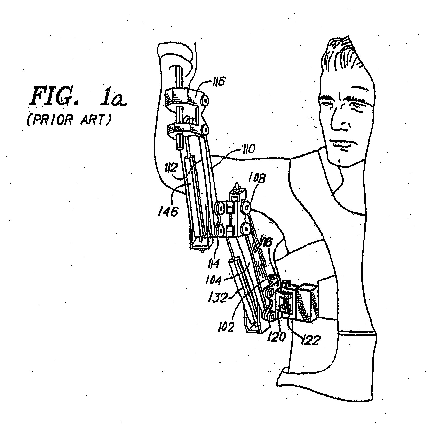
Figure 2 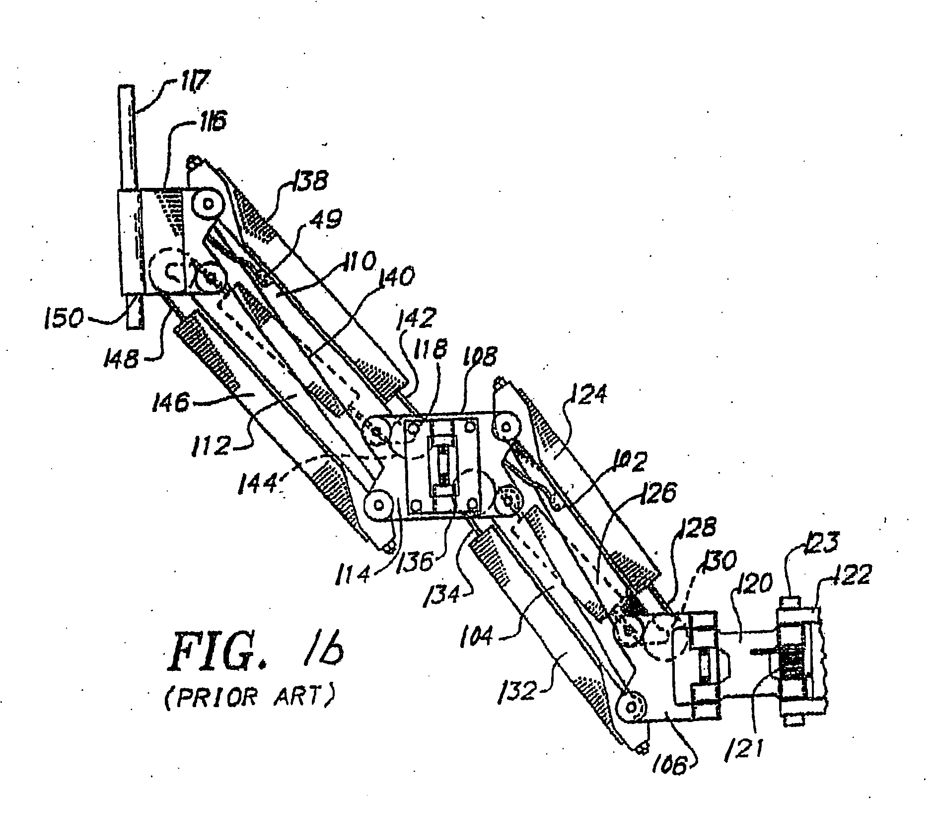
Figure 3
Abstract
Description
[0001] This application is based on, and claims priority to, provisional application Ser. No. 60 / 672,186, having a filing date of Apr. 15, 2005, and entitled, Auto Adjusting Equipoising Support Apparatus.BACKGROUND OF THE INVENTION
[0002] This invention relates generally to equipment supports, and more particularly to portable equipment utilized in conjunction with motion picture or video cameras.
[0003] Mobile film or video cameras typically require angular and spatial stability in order to obtain smooth, high-quality results. The Steadicam® portable camera stabilizing device, which has become a de facto standard in the TV and movie industry, was developed to permit stable ambulatory videography or cinematography by an operator. The inventor's U.S. Pat. No. 4,017,168 (Re. 32,213), U.S. Pat. Nos. 4,156,512 & 4,474,439 are directed to aspects of such stabilizing devices.
[0004] Spring powered ‘equipoising’ parallelogram arms have been used for decades to support and position payloads...
Examples
Embodiment Construction
[0057]FIGS. 1 and 2 illustrate a support apparatus of the prior art, which the inventor originally devised to obtain stabilized motion picture film and video images and which was offered for sale under the trademark “Steadicam®”. As illustrated, the support arm for the apparatus includes a pair of parallel upper arms links 102, 104, which are pivotally coupled at one end to a connector hinge bracket 106. The other ends of the upper arm links 102,104 are pivotally coupled to an upper arm medial hinge bracket 108. A second pair of parallel forearm links 110, 112 are pivotally coupled between a forearm medial bracket 114 and a camera support bracket 116. A camera mounting pin 117 is provided in the camera support bracket 116.
[0058] The upper arm medial bracket 108 and the forearm medial bracket 14 are rotatably coupled together along one side by a hinge 118. The connector hinge bracket 106 is rotatably coupled at its center to one end of a lower support hinge plate 120. The other end ...