
Top entry swing check valve
a check valve and swing technology, applied in the field of valves, can solve the problems of seat retainer pins being essentially chemically welded, seized or frozen in place, and add significant cost to the processes that require check valve control
Patent Information
- Authority / Receiving Office
- US · United States
- Patent Type
- Applications(United States)
- Current Assignee / Owner
- Publication Date
- 2008-12-18
- Estimated Expiration
- Not applicable · inactive patent
Smart Images
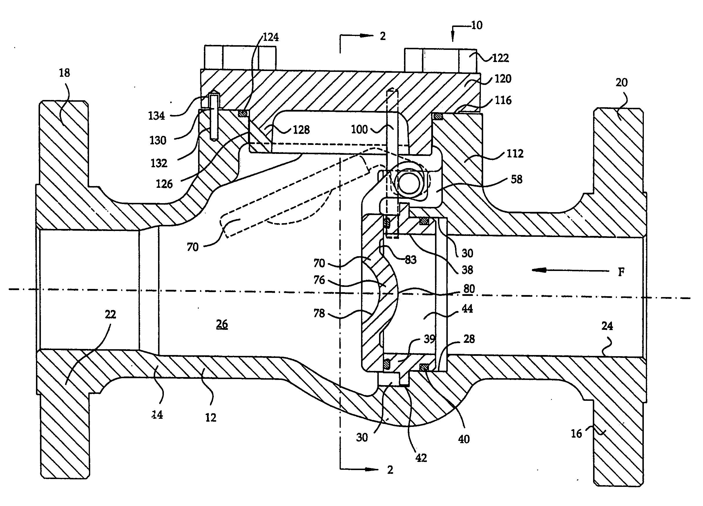
Figure 1 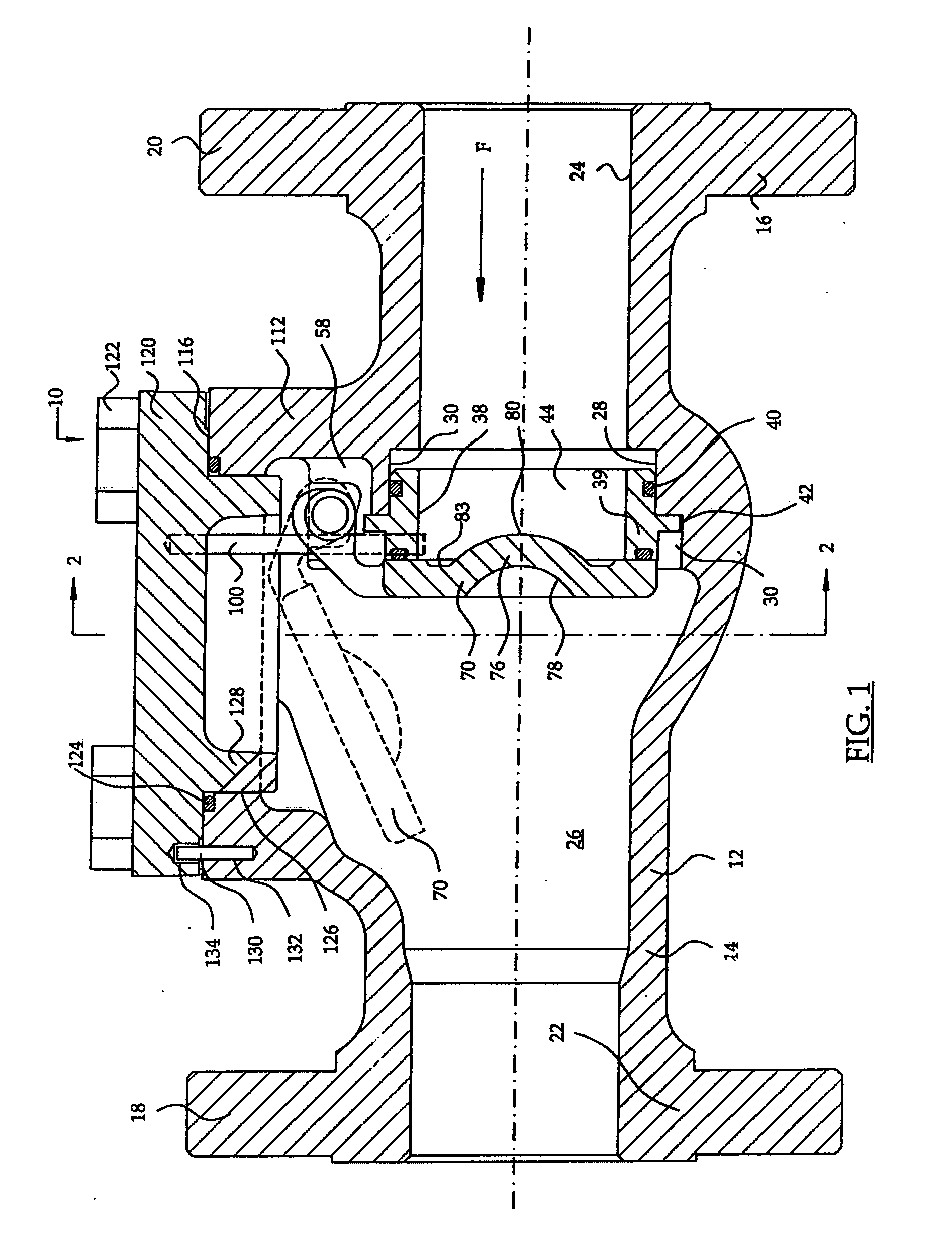
Figure 2 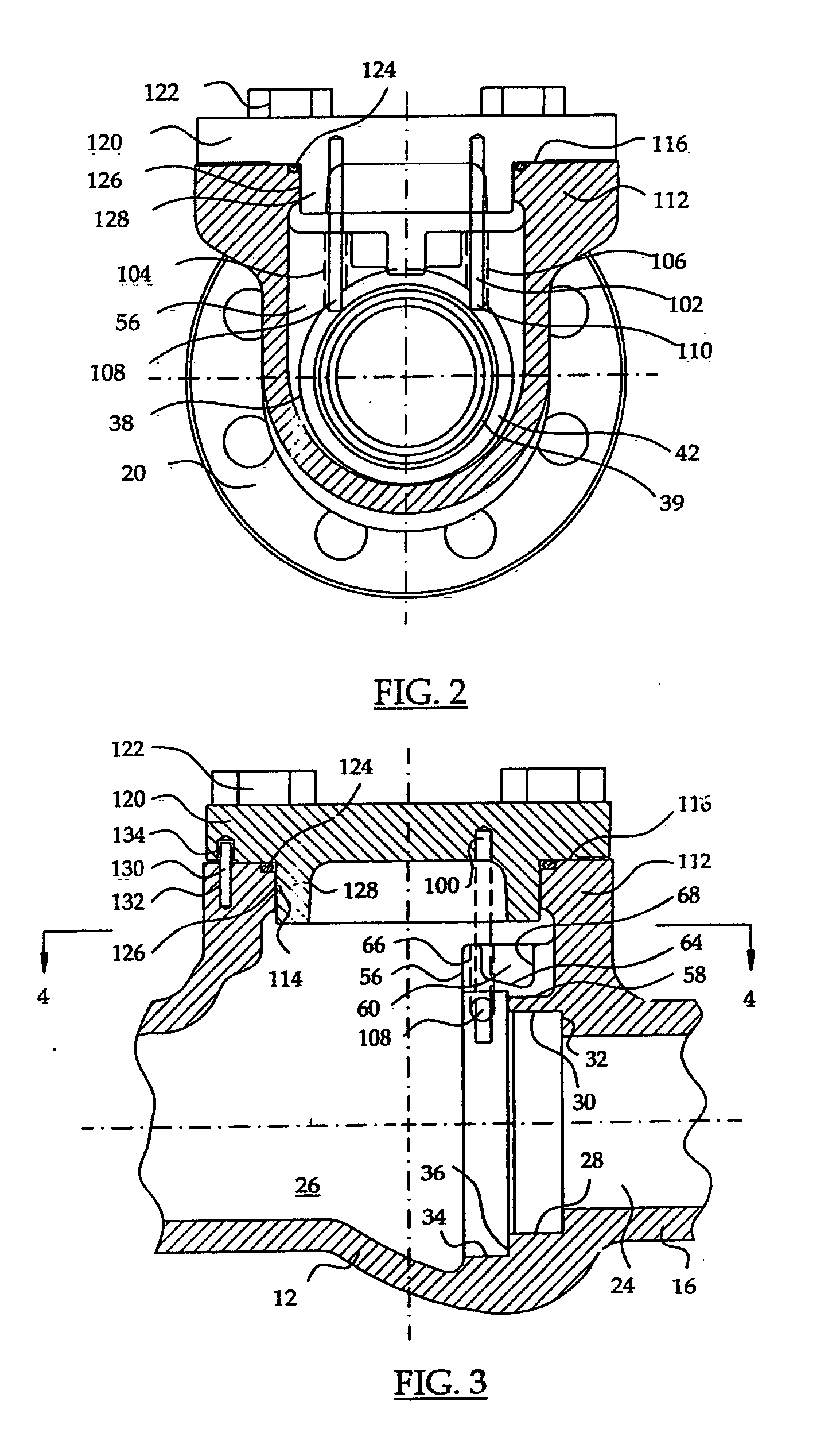
Figure 3
Abstract
Description
BACKGROUND OF THE INVENTION
[0001] 1. Field of the Invention
[0002] The present invention relates generally to valves for controlling the flow of fluids including liquids and gases and concerns swing check valves. More particularly, the present invention concerns a top entry swing check valve having a valve body defining an internal seat recess and having one or more seat retaining pins that are fixed to a removable bonnet defining a removable closure for the valve body. The seat retaining pins function to secure a check valve seat within a seat recess of the valve body. A bonnet orienting pin is employed to ensure proper positioning of the bonnet member relative to the valve body and also ensuring proper positioning of the seat retaining pins relative to the seat member. The present invention also concerns a alternative swing check valve construction that effectives lends itself to check valve mechanisms having a pivotally supported member carrying an annular sealing element which esta...
Examples
Embodiment Construction
[0029]Referring now to the drawings and first to FIGS. 1 and 2, a swing check valve mechanism is shown generally at 10 and comprises a valve body 12 having tubular connection members 14 and 16 each being provided with connection flanges 18 and 20 or other suitable means for connecting the valve mechanism into a flow line. The tubular connection members and connection flanges define internal flow passages 22 and 24 each communicating with a valve chamber 26 defined by the valve body 12 and communicating with the flow line within which the valve mechanism is connected.
[0030]With reference to FIGS. 1 and 3, within the valve body a circular seat recess 28 is defined by the valve body 12 and is located in substantially concentric relation with the flow passage 24. The seat recess is formed in part by a cylindrical surface 30 having intersection with an annular seat recess shoulder 32 and includes a concentric enlarged section 34 having an annular shoulder 36.
[0031]An annular valve seat a...