
Cooking grill shielding device
Patent Information
- Authority / Receiving Office
- US · United States
- Current Assignee / Owner
- Publication Date
- 2015-07-09
- Estimated Expiration
- Not applicable · inactive patent
Smart Images
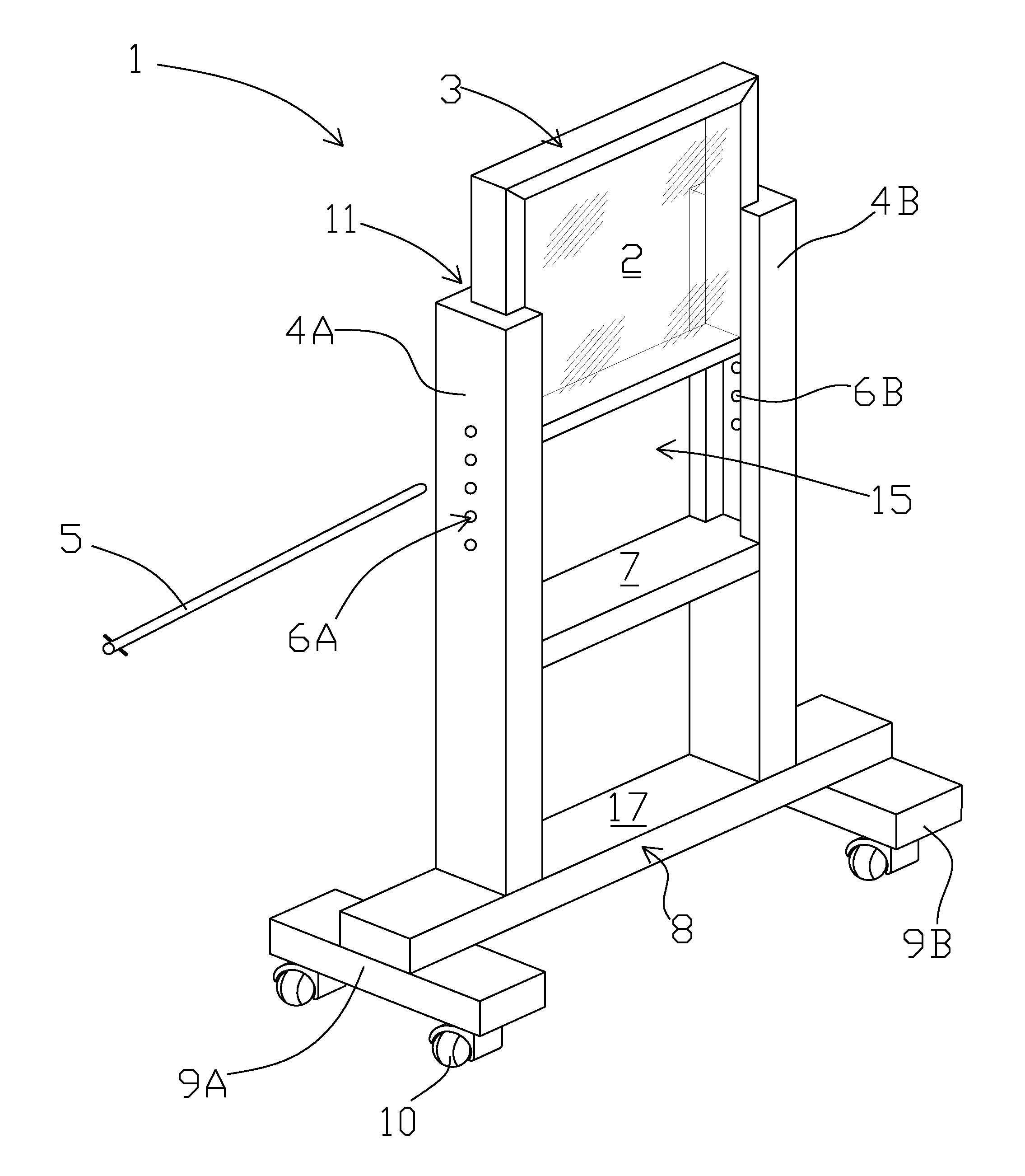
Figure 1 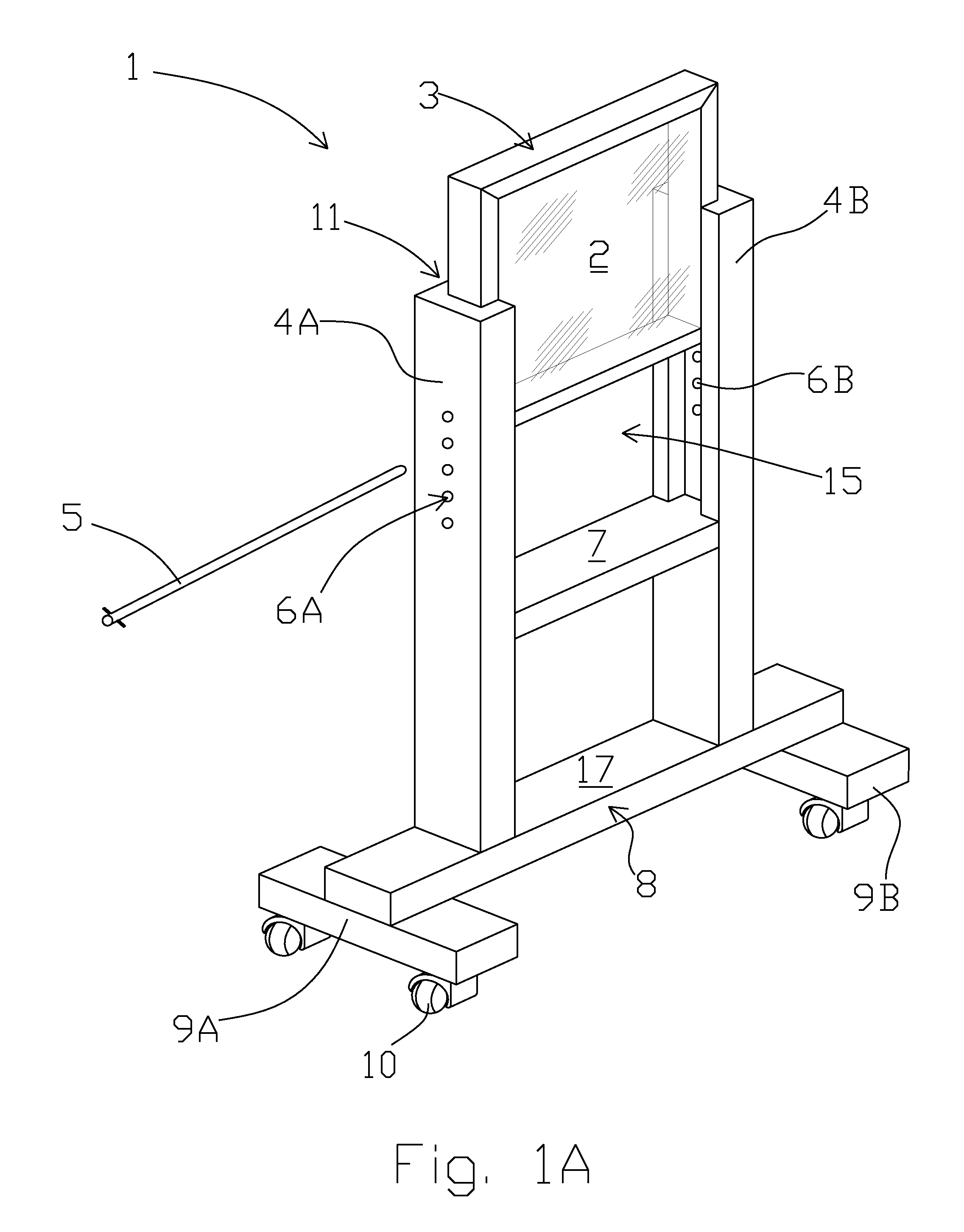
Figure 2 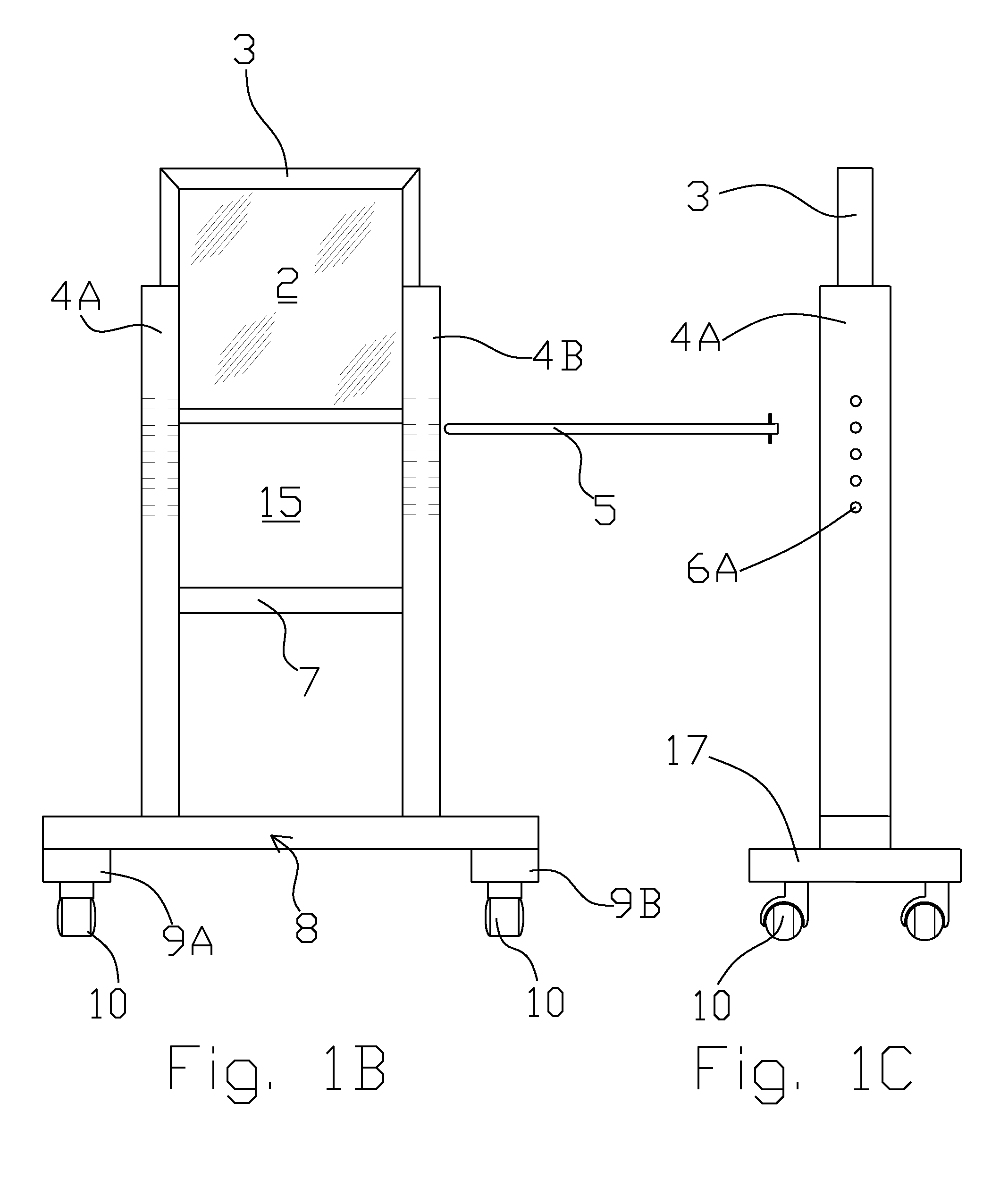
Figure 3
Abstract
Description
[0001] The present invention relates to U.S. Provisional Patent Application Ser. No. 61 / 964,539 filed on Jan. 9, 2014 and claims priority therefrom.
[0002] The present application was not subject to federal research and / or development funding.TECHNICAL FIELD
[0003] Generally, the invention relates to a protective device that shields a cook or other user's face and upper body from smoke, grease splatter and heat produced when grilling a food upon a grill. Specifically, the invention is a height-adjustable clear protective window arranged within a mobile frame and adjusted to a user's specific height such that the window is within the user's line of sight and between his face and the grilling surface. An access opening is arranged beneath the window and through which a user may pass his hands, food, and grilling utensils.BACKGROUND OF THE INVENTION
[0004] Many Americans use outdoor gas or charcoal grills to cook meals. Some hazards associated with the use of an outdoor grill are smoke, heat,...
Examples
second embodiment
[0026]FIGS. 2A-2C show the invention wherein the height adjustment pin 5 is substituted for a pair of shorter height adjustment pins 15A, 15B which extend into openings 6C, 6D. Openings 6C, 6D are perpendicular to those shown in FIGS. 1A-1C. In this embodiment, the first and second plurality of openings comprises four openings that are arranged at substantially the same elevation. The broken lines in FIG. 1B and FIG. 2C represent the openings 6A-6D and the portions of the vertical risers in which the openings are formed. As can be recognized, the user selects a desired height and inserts pins 15A and 15B into respective openings on the vertical risers.
third embodiment
[0027]FIG. 3A shows an embodiment of the invention wherein the base 8 comprises base members 9A, 9B and may be separated as indicated by the broken line. As more clearly shown in FIGS. 3B, 3C, one end includes a male end 25 having a complementary T-shape which snuggly fits within recess 30. In this manner, the device may be separated for ease in moving and storing the device. One end of the connecting member 24 is permanently fastened to one of the base member as shown in FIG. 3B. An opposite end of the connecting member 24 may be inserted into a recess in the opposite base member and locked into place to couple the pair of base members together. FIGS. 4A, 4B show a hinge 50 arranged between the base 9A and the vertical riser 4A. As can be understood, the base 9A may be rotated upwards for storage purposes. In the third embodiment, the bases 9A and 9B may have the vertical risers attached via a hinge to allow to raise ninety degress from horizontal for transport and storage.