
Optical imaging system
Patent Information
- Authority / Receiving Office
- US · United States
- Current Assignee / Owner
- Publication Date
- 2019-12-05
Smart Images
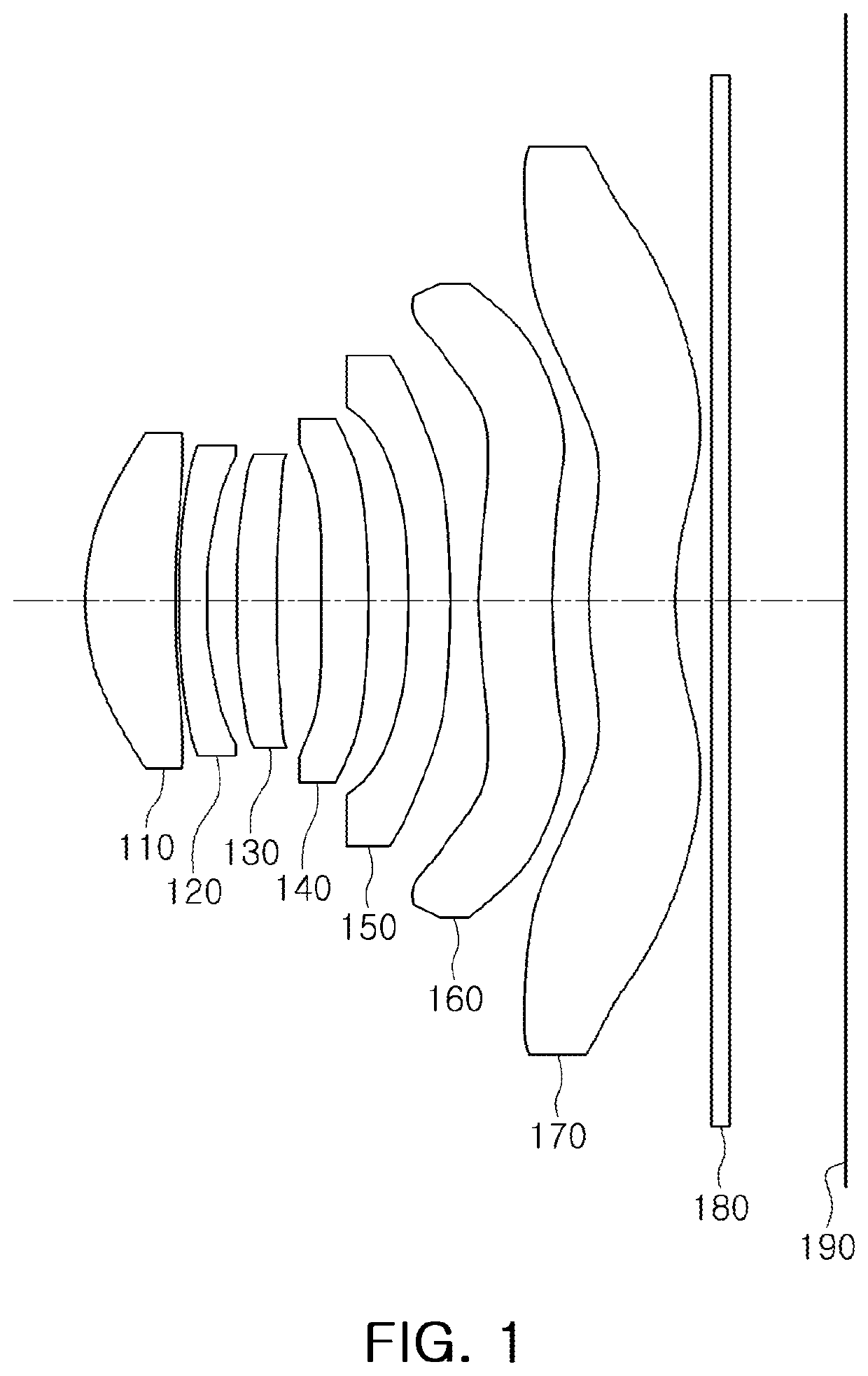
Figure 1 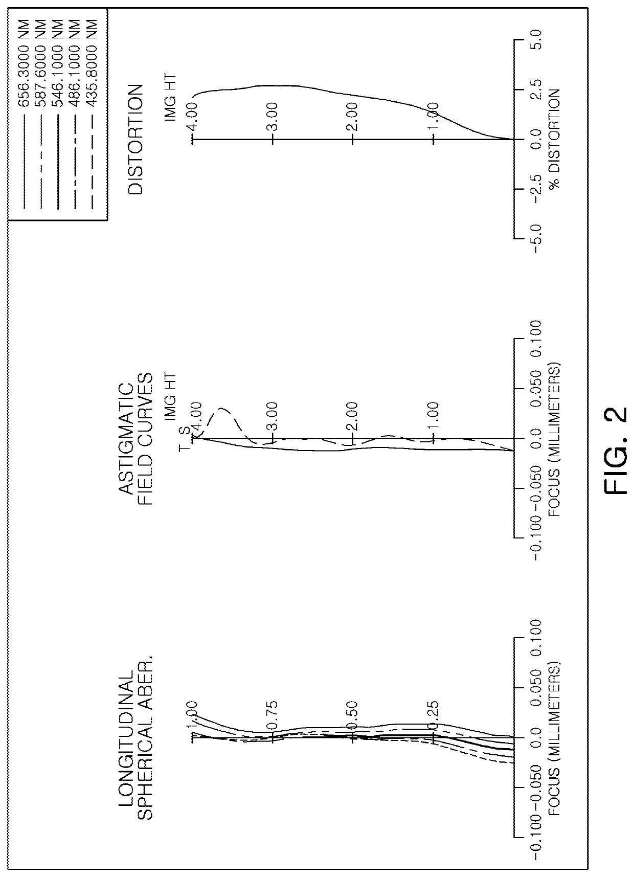
Figure 2 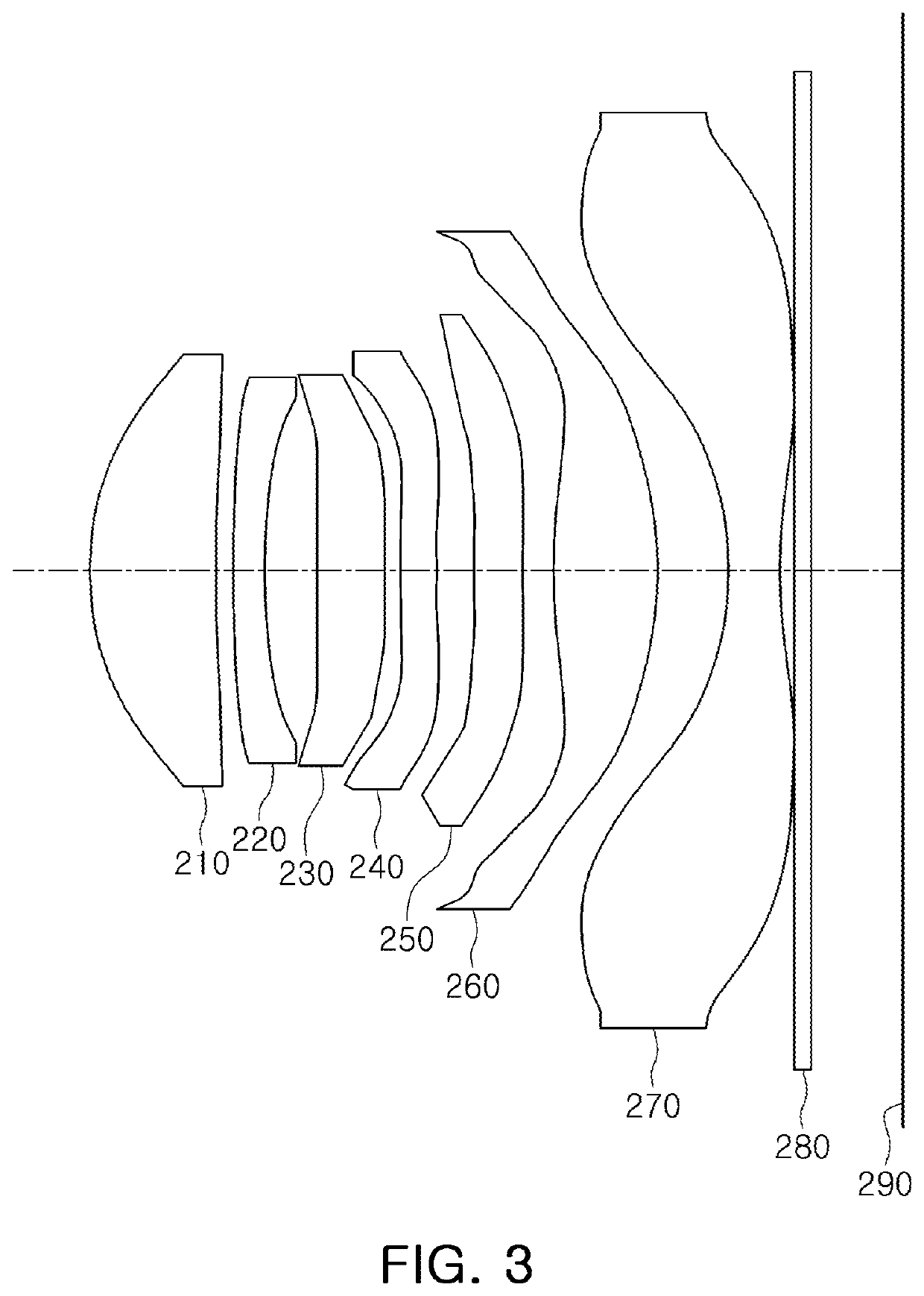
Figure 3
Abstract
Description
CROSS-REFERENCE TO RELATED APPLICATIONS
[0001] This application claims the benefit under 35 USC 119(a) of Korean Patent Application Nos. 10-2018-0061412 filed on May 29, 2018, and 10-2018-0106169 filed on Sep. 5, 2018, in the Korean Intellectual Property Office, the entire disclosures of which are incorporated herein by reference for all purposes.BACKGROUND1. Field
[0002] This application relates to an optical imaging system.2. Description of Related Art
[0003] Recently, mobile communications terminals have been provided with camera modules, enabling video calling and image capturing. In addition, as utilization of the camera modules mounted in the mobile communications terminals has increased, camera modules for the mobile communications terminals have gradually been required to have high resolution and performance.
[0004] Therefore, the number of lenses included in the camera module has increased. However, since the mobile communications terminal in which the camera module is mounted tend...
Examples
sixth example
[0271]FIG. 11 is a view illustrating a sixth example of an optical imaging system, and FIG. 12 illustrates aberration curves of the optical imaging system of FIG. 11.
[0272]The sixth example of the optical imaging system includes a first lens 610, a second lens 620, a third lens 630, a fourth lens 640, a fifth lens 650, a sixth lens 660, a seventh lens 670, an infrared cut-off filter 680, an image sensor 690, and a stop (not shown) between the first lens 610 and the second lens 620.
[0273]The first lens 610 has a negative refractive power, a paraxial region of an object-side surface thereof is convex, and a paraxial region of an image-side surface thereof is concave.
[0274]The second lens 620 has a positive refractive power, a paraxial region of an object-side surface thereof is convex, and a paraxial region of an image-side surface thereof is concave.
[0275]The third lens 630 has a negative refractive power, a paraxial region of an object-side surface thereof is convex, and a paraxial ...
seventh example
[0284]FIG. 13 is a view illustrating a seventh example of an optical imaging system, and FIG. 14 illustrates aberration curves of the optical imaging system of FIG. 13.
[0285]The seventh example of the optical imaging system includes a first lens 710, a second lens 720, a third lens 730, a fourth lens 740, a fifth lens 750, a sixth lens 760, a seventh lens 770, an infrared cut-off filter 780, an image sensor 790, and a stop (not shown) between the first lens 710 and the second lens 720.
[0286]The first lens 710 has a negative refractive power, a paraxial region of an object-side surface thereof is convex, and a paraxial region of an image-side surface thereof is concave.
[0287]The second lens 720 has a positive refractive power, a paraxial region of an object-side surface thereof is convex, and a paraxial region of an image-side surface thereof is concave.
[0288]The third lens 730 has a negative refractive power, a paraxial region of an object-side surface thereof is convex, and a parax...
eighth example
[0297]FIG. 15 is a view illustrating an eighth example of an optical imaging system, and FIG. 16 illustrates aberration curves of the optical imaging system of FIG. 15.
[0298]The eighth example of the optical imaging system includes a first lens 810, a second lens 820, a third lens 830, a fourth lens 840, a fifth lens 850, a sixth lens 860, a seventh lens 870, an infrared cut-off filter 880, an image sensor 890, and a stop (not shown) disposed between the first lens 810 and the second lens 820.
[0299]The first lens 810 has a positive refractive power, a paraxial region of an object-side surface thereof is convex, and a paraxial region of an image-side surface thereof is concave.
[0300]The second lens 820 has a negative refractive power, a paraxial region of an object-side surface thereof is convex, and a paraxial region of an image-side surface thereof is concave.
[0301]The third lens 830 has a negative refractive power, a paraxial region of an object-side surface thereof is convex, and...