
Wiring structure of wire harness and wire harness
a wire harness and wire harness technology, applied in the direction of insulated conductors, cables, electric/fluid circuits, etc., can solve the problems of reduced fixing force, inability to secure sufficient adhesion area, and electric wires moving in flexible sheets, etc., to achieve stable fixing strength and reliable maintenance
Patent Information
- Authority / Receiving Office
- US · United States
- Patent Type
- Applications(United States)
- Current Assignee / Owner
- Publication Date
- 2021-10-07
Smart Images
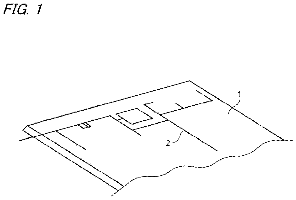
Figure 1 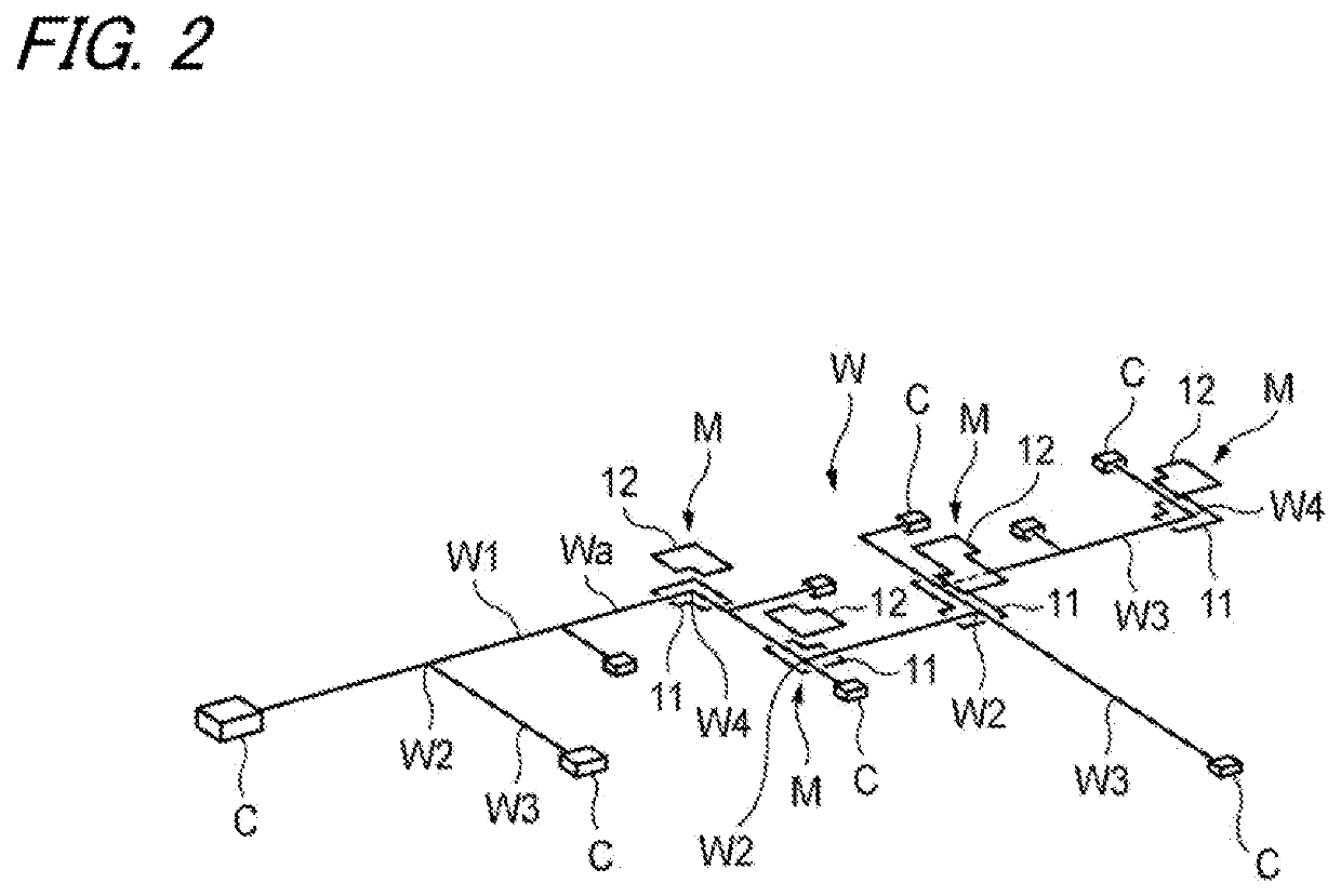
Figure 2 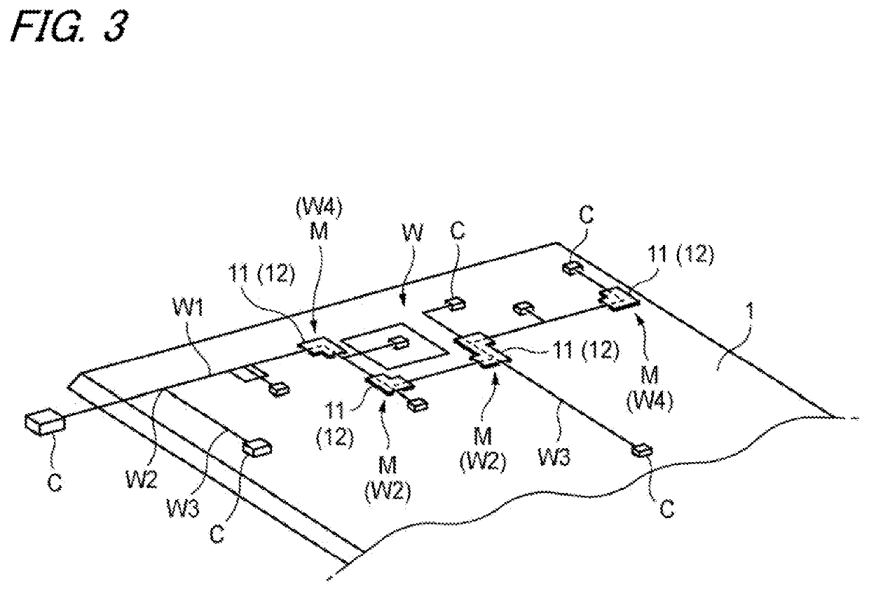
Figure 3
Abstract
Description
CROSS REFERENCE TO RELATED APPLICATIONS
[0001] This application is based on and claims priority from Japanese patent application No. 2020-069250 filed on Apr. 7, 2020, the entire contents of which are incorporated herein by reference.TECHNICAL FIELD
[0002] The present invention relates to a wiring structure of a wire harness in an automobile roof portion and a wire harness for an automobile roof portion.BACKGROUND ART
[0003] A roof portion of an automobile is provided with a roof panel constituting an upper surface of a roof portion and a roof lining mounted on the roof panel and constituting a lower surface of the roof portion. A wire harness is wired in a space between the roof panel and the roof lining, and electric power is supplied to a room lamp or the like via the wire harness.
[0004] Incidentally, for example, as in Patent Literatures 1 and 2, a wire harness wired in a roof portion of an automobile is fixed in a desired wiring path by being pressed and adhered and fixed to an adhesi...
Examples
Embodiment Construction
[0029]Specific embodiments according to the present invention will be described below with reference to the accompanying drawings.
[0030]FIG. 1 is a perspective view showing a state of an upper surface of a roof lining before a wire harness for an automobile roof portion according to an embodiment of the present invention is fixed to a roof lining, FIG. 2 is a perspective view showing a state in which tapes which sandwich an electric wire are disposed at predetermined positions of the wire harness, FIG. 3 is a perspective view showing a wiring structure of the wire harness in the automobile roof portion according to the embodiment of the present invention, and FIG. 4 is an enlarged cross-sectional view of restraint portions by the tapes of FIG. 3.
[0031]As shown in FIG. 4, a wire harness W for an automobile roof portion of the present embodiment is fixed to and wired on an adhesive member (double-sided adhesive tape 2) laid on a surface of a roof lining 1 of an automobile. Therefore, ...