
Interior illuminator for automobile
a technology for interior illumination and automobiles, applied in fixed installations, lighting and heating apparatus, instruments, etc., can solve the problems of uneven illumination light in the illumination range, disadvantageous protruding of light bulbs into the interior of automobiles, heat generation, power consumption, etc., and achieves efficient use, high color, and broadening the relatively high directivity of light emitted
Patent Information
- Authority / Receiving Office
- US · United States
- Patent Type
- Patents(United States)
- Current Assignee / Owner
- Publication Date
- 2007-10-30
- Estimated Expiration
- Not applicable · inactive patent
Smart Images
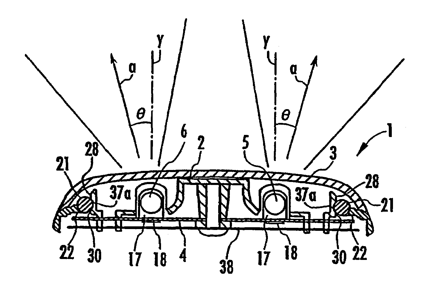
Figure 1 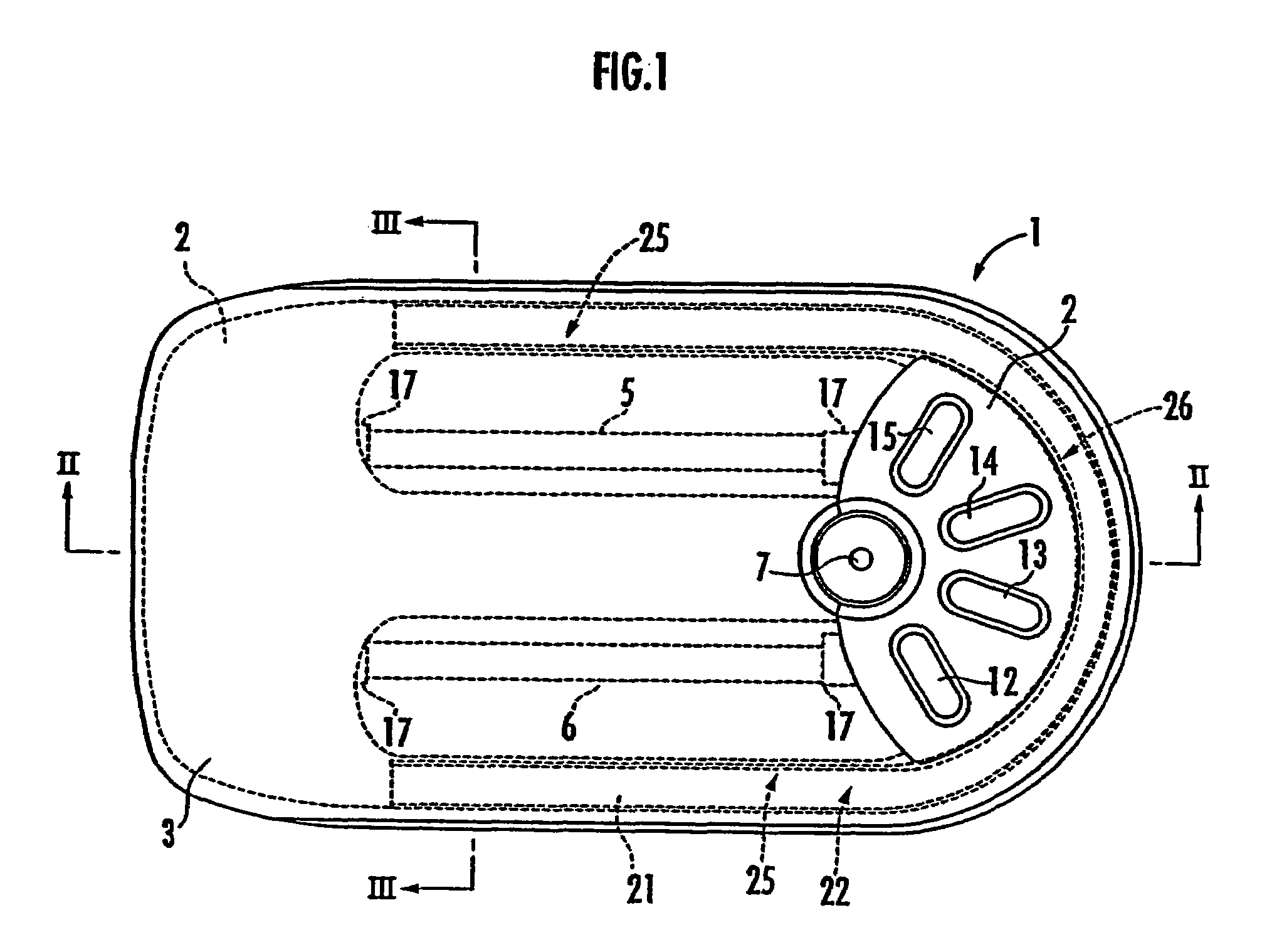
Figure 2 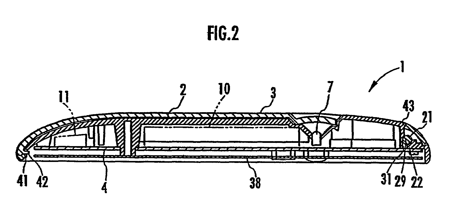
Figure 3
Abstract
Description
BACKGROUND OF THE INVENTION
[0001] 1. Field of the Invention
[0002] The present invention relates to an interior illuminator for an automobile which is provided on the ceiling of the automobile and illuminates the interior of the automobile.
[0003] 2. Description of the Related Art
[0004] A conventional known illuminator for illuminating the interior of an automobile uses a light bulb as a light source. The illuminator of this type is attached to the ceiling of the automobile and illuminates the interior when a switch is manipulated by an occupant or when a door switch is turned on by the opening of a door. However, in the case of using a light bulb as the light source, the light bulb has to be a large one to achieve an adequate light quantity, and therefore, the light bulb disadvantageously protrudes significantly into the interior of the automobile. To avoid this, a plurality of small light bulbs may be used to achieve the same light quantity as the large one. In this case, however, there...
Examples
Embodiment Construction
[0032]An embodiment of the present invention will be described with reference to the drawings. FIG. 1 is a plan view of an illuminator according to this embodiment, FIG. 2 is a cross sectional view of the illuminator taken along the line II-II in FIG. 1, FIG. 3 is a cross sectional view of the illuminator taken along the line III-III in FIG. 1, FIG. 4 is a plan view of a circuit board, FIG. 5 is a cross sectional view of a part of the circuit board, FIG. 6 is a plan view of a housing, FIG. 7 is a cross sectional view of the housing taken along the line VII-VII in FIG. 6, FIG. 8 is a cross sectional view of the housing being formed taken along the line VIII-VIII in FIG. 6, FIG. 9 is a cross sectional view of the housing being formed taken along the line IX-IX in FIG. 6, FIG. 10 is an exploded perspective view of the illuminator according to this embodiment, FIG. 11 is a plan view of an optically transparent cover, FIG. 12 is a cross sectional view of the illuminator attached to the c...