
Connector having a locking lance
a technology of connecting rods and lances, which is applied in the direction of testing/measuring connectors, coupling device connections, and securing/insulating coupling contact members
Patent Information
- Authority / Receiving Office
- US · United States
- Patent Type
- Patents(United States)
- Current Assignee / Owner
- Publication Date
- 2011-01-04
- Estimated Expiration
- Not applicable · inactive patent
Smart Images
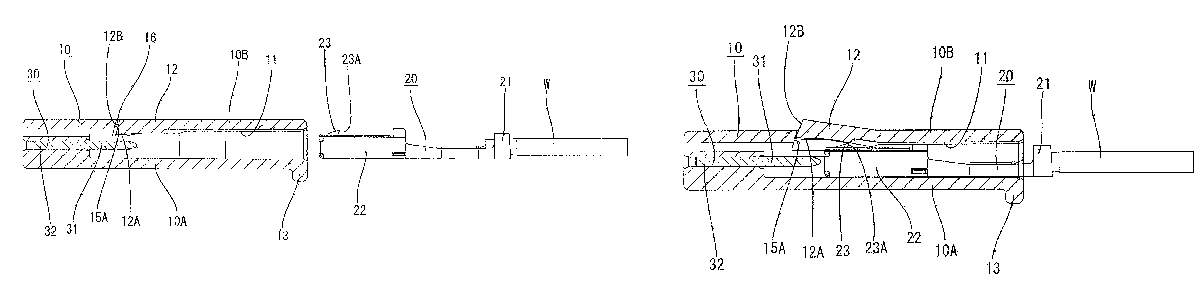
Figure 1 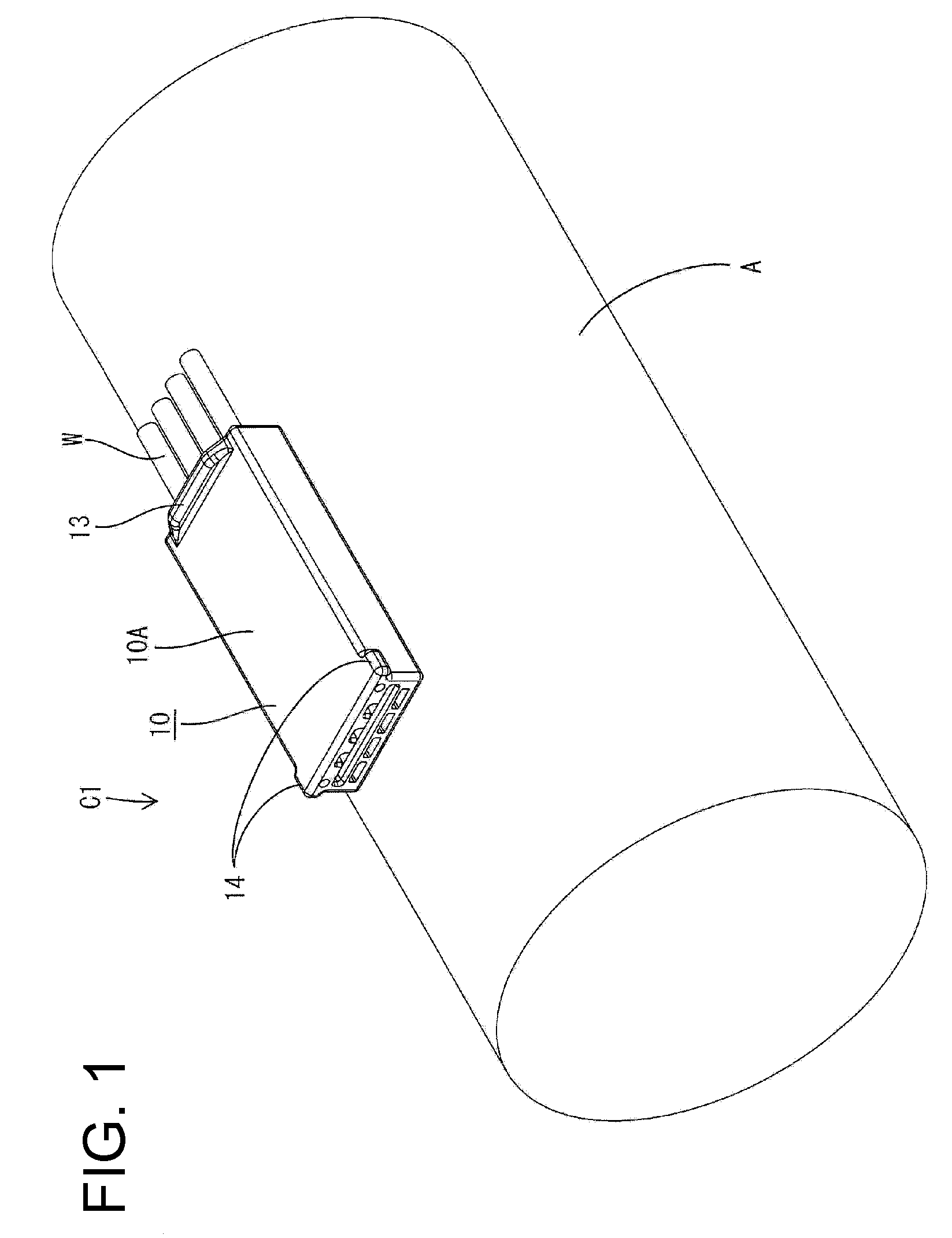
Figure 2 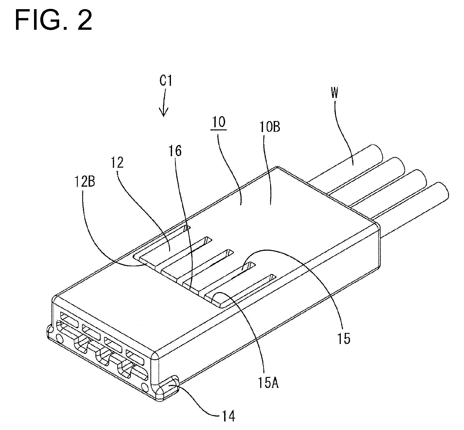
Figure 3
Abstract
Description
BACKGROUND OF THE INVENTION
[0001] 1. Field of the Invention
[0002] The invention relates to a connector formed with a locking lance in an outer wall of a housing.
[0003] 2. Description of the Related Art
[0004] Japanese Unexamined Patent Publication No. 2004-14220 and other known prior art show connectors that have a housing and a terminal held in the housing by a locking lance. The locking lance of Japanese Unexamined Patent Publication No. 2004-14220 is formed at an outer wall of the housing and is resiliently deformable in inward and outward directions of the housing. The locking lance is deformed outwardly upon inserting a terminal into a cavity, but resiliently returns inwardly toward to engage the terminal when the terminal reaches a proper position in the cavity. A jig can engage the leading end of the locking lance to deform the locking lance outwardly and out of engagement with the terminal so that the terminal can be withdrawn from the cavity. However, the jig can cause the locki...
Examples
first embodiment
[0041]A connector in accordance with the invention is identified as C1 in FIGS. 1 to 12. The connector C1 is a joint connector and has a housing 10 internally formed with cavities 11 capable of accommodating terminals 20. The housing has locking lances 12 for engaging the respective terminals 20 that have been inserted properly into the cavities 11 and retaining the terminals 20 in the cavities 11. The connector C1 also has at least one busbar 30 for shorting the terminals 20 in the cavities 11. The connector C1 is fixed to a main line A of a wiring harness by tape (not shown). A side of the connector C1 to be connected with a mating connector is referred to as the front and left-lower, right-upper, upper and lower sides of FIG. 1 are referred to as front, rear, top and lower sides in the respective constituent elements.
[0042]The housing 10 is made e.g. of synthetic resin and has a substantially flat box shape. A rib 13 is provided on a top wall 10A of the housing 10, which is on a ...
third embodiment
[0070]The branch connection may be with a device-side wire W1 that is to be connected electrically with an external electric or electronic device (such as a junction box, a load, a sensor or the like). A nonconductive film, such as an oxide film, is likely to be formed on the outer surface of the aluminum wire. The film on the outer surface typically cannot be scraped off sufficiently merely by pressing the wire between contact blades of an insulation displacement terminal and problems, such as a connection error and an increase of contact resistance, are likely to occur (see, for example, Japanese Unexamined Patent Publication No. 2007-87861). Thus, a crimping connection is preferred for an aluminum wire. For the above reason, a connector C1 of the third embodiment has a cavity 11 and a terminal 20 that is crimped, bent or folded into connection with an end portion of the branch line B is inserted into the cavity 11.
[0071]As shown in FIG. 18, the wiring harness WH includes the main...
second embodiment
[0080]The catches 50 are recesses formed in the leading end surfaces of the locking lances 12 in the However, the catches may be of any form provided that they are engageable with the leading end of the disengaging jig. For example, a plurality of fine lateral grooves or a plurality or projections may be formed at the leading ends of the locking lances.
[0081]Although the main line A1 made up of the aluminum wires is illustrated in the third and fourth embodiments, a main line made up of copper wires may be used according to the present invention. In this case, the branch line B and the device-side wire W1 may be connected directly connected using an insulation displacement terminal instead of using the terminals 20 and the busbar 30.