
Constant velocity joint of tripod type
a constant velocity joint and tripod technology, applied in the direction of shafts, bearings, shafts for rotary movement, etc., can solve the problems of large friction between the faces, increased production costs, and increased production costs, and achieve the effect of reducing conventional shudder or frictional contact problems and sufficient durability
Patent Information
- Authority / Receiving Office
- US · United States
- Patent Type
- Patents(United States)
- Current Assignee / Owner
- Publication Date
- 2011-09-27
Smart Images
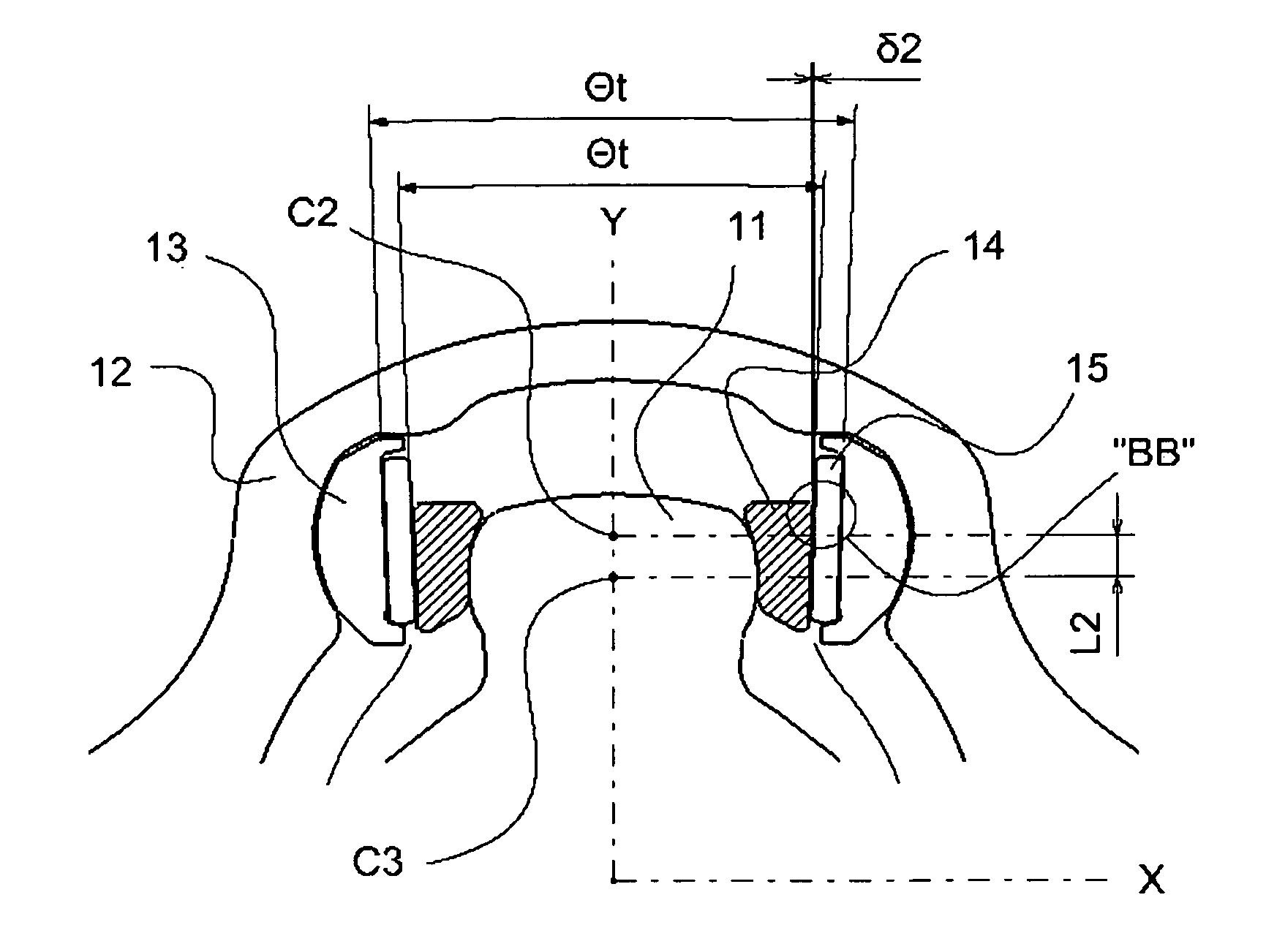
Figure 1 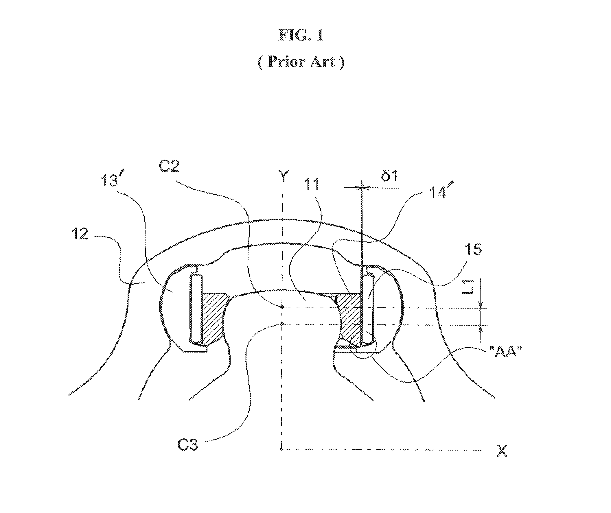
Figure 2 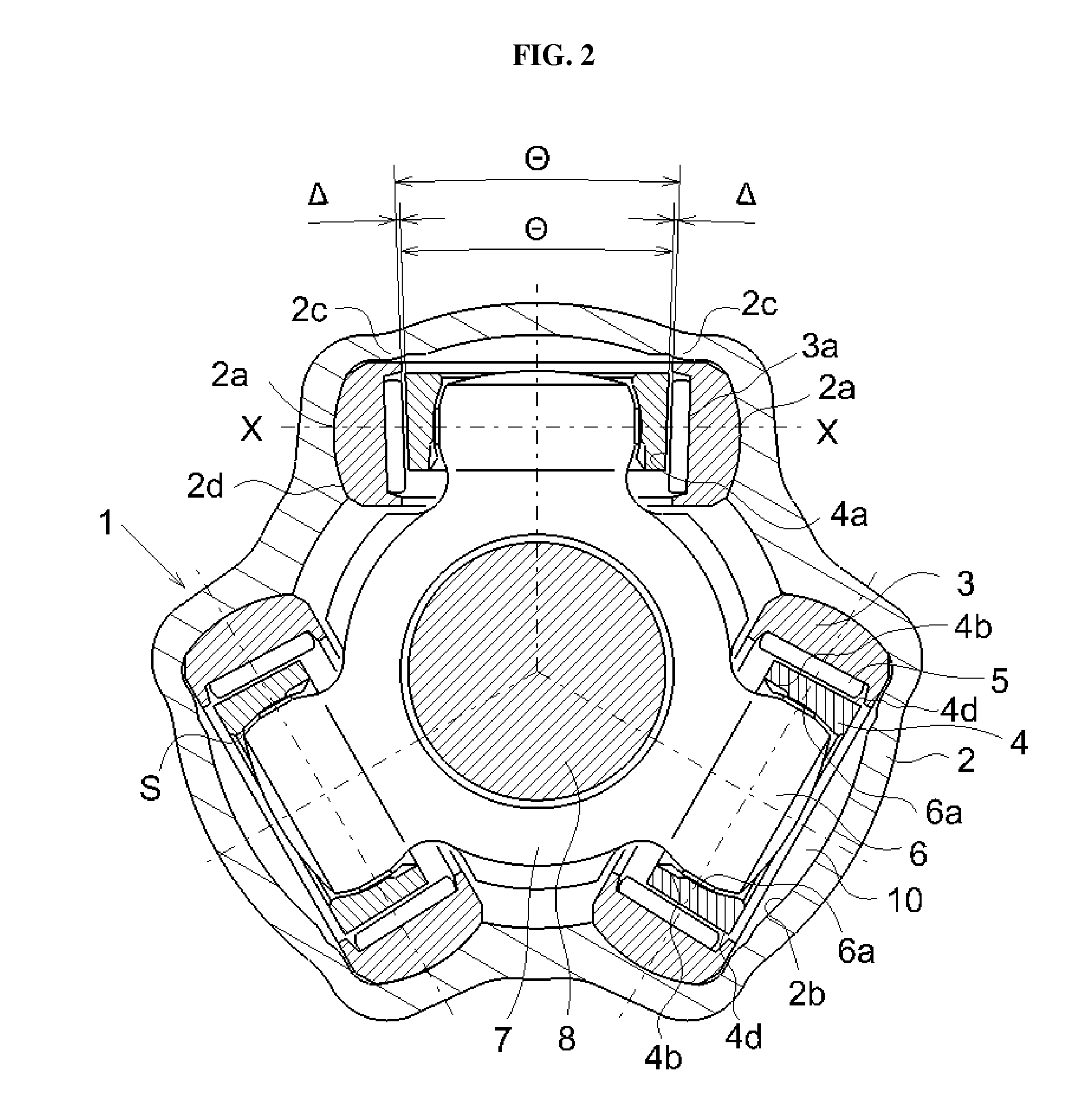
Figure 3
Abstract
Description
REFERENCE TO RELATED APPLICATION
[0001] The present application is a continuation-in-part of U.S. patent application Ser. No. 11 / 750,138, entitled “CONSTANT VELOCITY JOINT OF TRIPOD TYPE” and filed on May 17, 2007 (now U.S. Pat. No. 7,819,752), which was filed by the applicant (namely, an inventor of this application) and assigned to the same assignee as the present application, the content of which is incorporated herein by reference in its entirety.FIELD OF THE INVENTION
[0002] The present invention relates to a constant velocity joint of tripod type, which is disposed between a drive shaft and a driven shaft coupled to each other and typically used in a drive axle of, for example, an automobile for transmitting rotational torque between the rotating shafts.BACKGROUND OF THE INVENTION
[0003] Tripod type constant velocity joints are well known in the automobile industry as one type of constant velocity joints used in the drive system of vehicles for transferring a uniform torque and a co...
Examples
Embodiment Construction
[0042]Referring to the drawings, the tripod type constant velocity joints of the present invention are described herein in further details with several exemplary or preferred embodiments thereof. However, the following descriptions of such embodiments are intended primarily for illustrating the principles and exemplary constructions of the constant velocity joints of the present invention, and the present invention is not specifically limited to these exemplary embodiments. Thus, one skilled in the art can appreciate or recognize that various modifications and substitutions can be made thereto without departing from the spirit and scope of the present invention.
[0043]The present invention is associated with and claims priority over Applicant's previous application Ser. No. 11 / 750,138. Accordingly, the entire contents of this application are incorporated herein by reference, and the detailed descriptions of the constant velocity joints of this application are not repeated herein for ...