
Pipe flange forming method
a flange and pipe technology, applied in the direction of flanged joints, mechanical equipment, other domestic objects, etc., can solve the problems of cracks and breakage, welding steps require additional labor and costs, etc., to reduce or eliminate the risk of breakage, reduce the risk of part loss, and reduce manufacturing costs
Patent Information
- Authority / Receiving Office
- US · United States
- Patent Type
- Patents(United States)
- Current Assignee / Owner
- Publication Date
- 2013-09-17
Smart Images

Figure 1 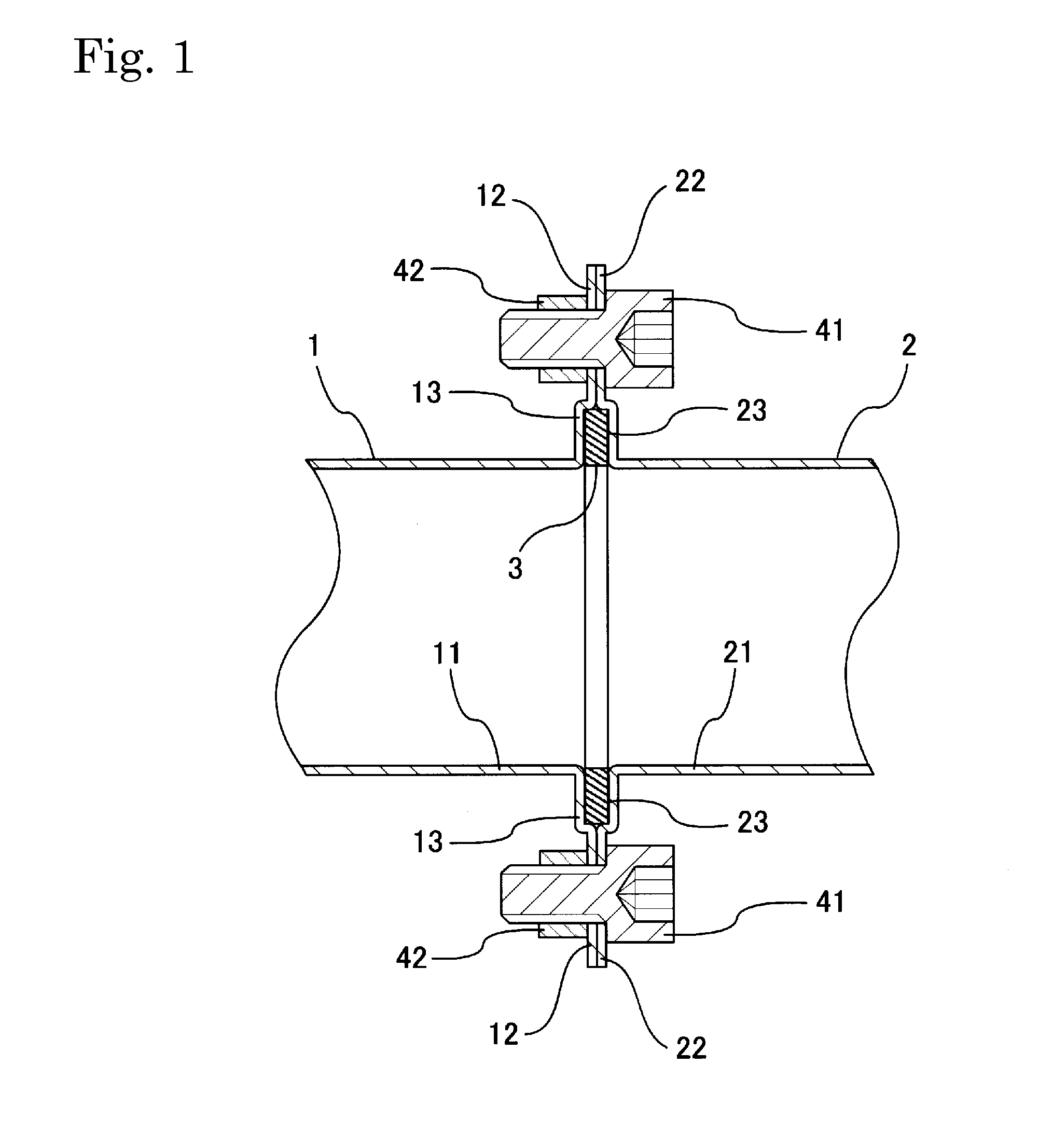
Figure 2 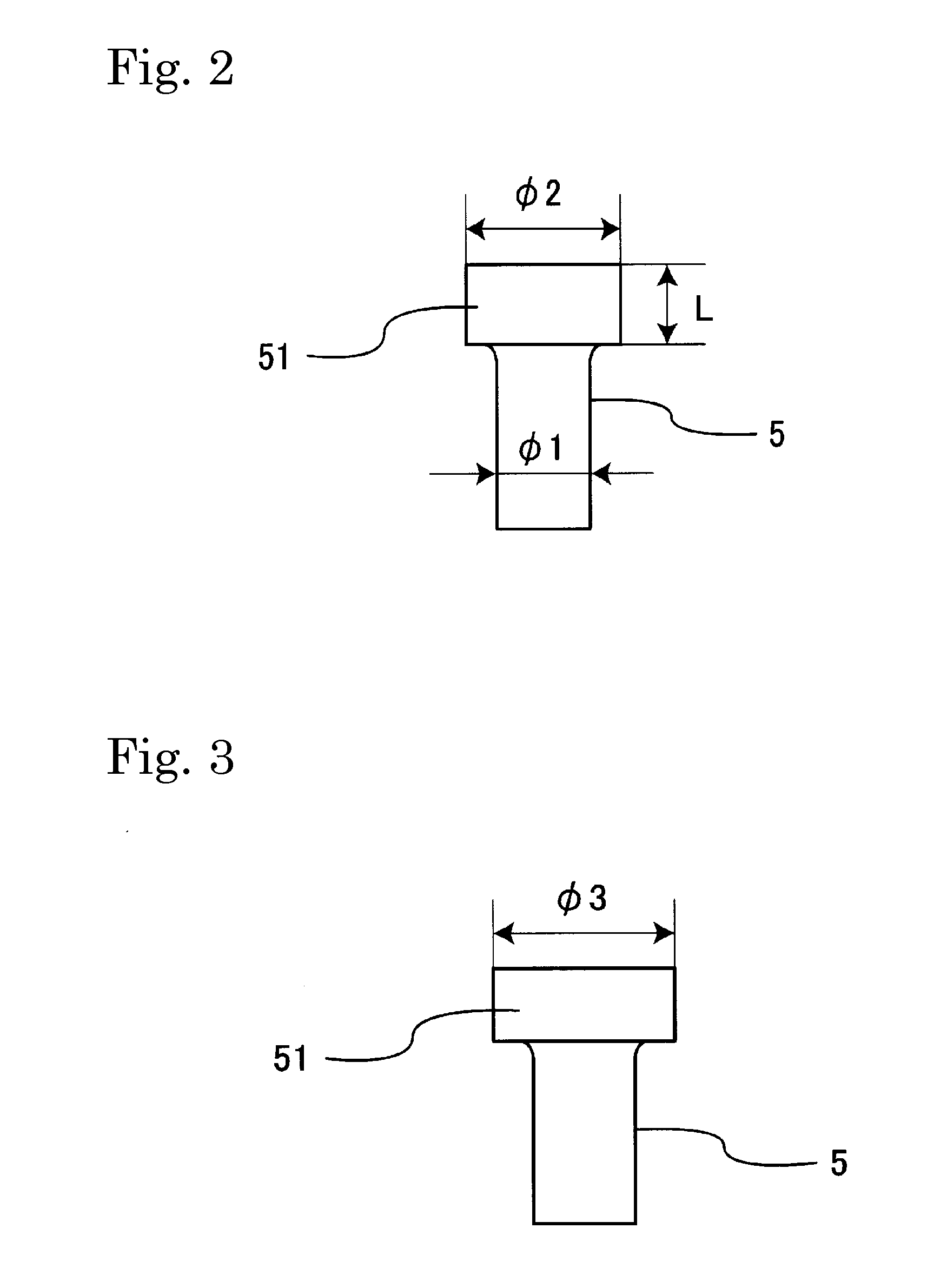
Figure 3
Abstract
Description
BACKGROUND OF THE INVENTION
[0001] 1. Field of the Invention
[0002] The present invention relates to a method for forming a flange on an open end of a pipe, e.g., for vehicle exhaust pipes.
[0003] 2. Description of the Related Art
[0004] FIGS. 11 and 12 show an example of a known vehicle exhaust pipe coupling structure. In FIG. 12, approximately rhombic-shaped coupling flanges 61, 62 (see FIG. 11) are welded to the outer peripheral ends of an upstream exhaust pipe 1 and a downstream exhaust pipe 2, respectively. A gasket 63 disposed between the coupling flanges 61, 62 and the exhaust pipes 1 and 2 are joined using bolts 64 and nuts 65.
[0005] Japanese Laid-Open Patent Publication No. H8-75063 discloses a connecting structure for an exhaust pipe, in which flanges are welded to the respective outer peripheries of a first exhaust pipe and a second exhaust pipe. The second exhaust pipe is fitted into the opening of one end of the first exhaust pipe. The flanges are joined by bolts and nuts.
[0006] ...
Examples
Embodiment Construction
[0025]FIG. 1 shows a representative example of an upstream exhaust pipe 1 joined to a downstream exhaust pipe 2 via pipe-end flanges 12, 22 formed in accordance with the below-described method. More specifically, radially-outwardly-extending pipe-end flanges 12 and 22 are formed at an opening edge of an opening of a downstream end 11 of the upstream exhaust pipe 1 and at an opening edge of an opening of an upstream end 21 of the downstream exhaust pipe 2, respectively. The pipe-end flanges 12 and 22 are coupled together via bolts 41 and nuts 42 with a sealing member or gasket 3 interleaved in a space defined by recessed housing portions 13 and 23. The pipes 1, 2 and flanges 12, 22 are preferably formed of malleable steel, although other heat-resistant, malleable materials may be utilized for vehicle applications. For non-vehicle applications, the material forming the pipe 1, 2 and flange 12, 22 need not be heat-resistant, but it should be ductile or malleable, i.e. it should be plas...