
Pipe flange forming method
Patent Information
- Authority / Receiving Office
- US · United States
- Current Assignee / Owner
- Publication Date
- 2012-06-28
Smart Images
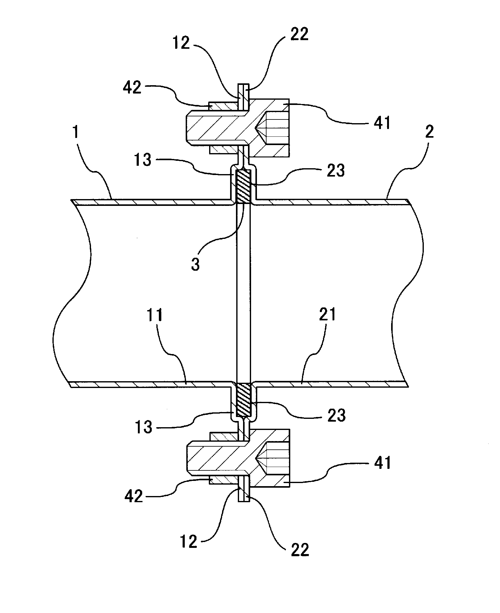
Figure 1 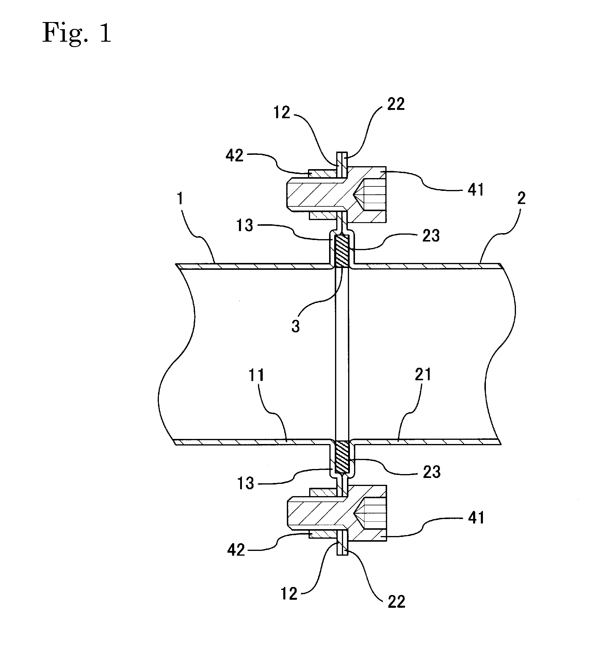
Figure 2 
Figure 3
Abstract
Description
BACKGROUND OF THE INVENTION
[0001] 1. Field of the Invention
[0002] The present invention relates to a method for forming a flange on an open end of a pipe, e.g., for vehicle exhaust pipes.
[0003] 2. Description of the Related Art
[0004] FIGS. 11 and 12 show an example of a known vehicle exhaust pipe coupling structure. In FIG. 12, approximately rhombic-shaped coupling flanges 61, 62 (see FIG. 11) are welded to the outer peripheral ends of an upstream exhaust pipe 1 and a downstream exhaust pipe 2, respectively. A gasket 63 disposed between the coupling flanges 61, 62 and the exhaust pipes 1 and 2 are joined using bolts 64 and nuts 65.
[0005] Japanese Laid-Open Patent Publication No. H8-75063 discloses a connecting structure for an exhaust pipe, in which flanges are welded to the respective outer peripheries of a first exhaust pipe and a second exhaust pipe. The second exhaust pipe is fitted into the opening of one end of the first exhaust pipe. The flanges are joined by bolts and nuts.
[0006] ...
Examples
Embodiment Construction
[0025]FIG. 1 shows a representative example of an upstream exhaust pipe 1 joined to a downstream exhaust pipe 2 via pipe-end flanges 12, 22 formed in accordance with the below-described method. More specifically, radially-outwardly-extending pipe-end flanges 12 and 22 are formed at an opening edge of an opening of a downstream end 11 of the upstream exhaust pipe 1 and at an opening edge of an opening of an upstream end 21 of the downstream exhaust pipe 2, respectively. The pipe-end flanges 12 and 22 are coupled together via bolts 41 and nuts 42 with a sealing member or gasket 3 interleaved in a space defined by recessed housing portions 13 and 23. The pipes 1, 2 and flanges 12, 22 are preferably formed of malleable steel, although other heat-resistant, malleable materials may be utilized for vehicle applications. For non-vehicle applications, the material forming the pipe 1, 2 and flange 12, 22 need not be heat-resistant, but it should be ductile or malleable, i.e. it should be plas...