

Braking control device
a control device and braking technology, applied in the direction of electric devices, braking systems, tractors, etc., can solve the problems of increasing the fluctuation of vehicle deceleration, restricting the amount of regenerative braking, and affecting the behavior of vehicles, so as to suppress the uncomfortable sensation of drivers, inhibit the change of vehicle behavior, and reduce the effect of vehicle deceleration
Patent Information
- Authority / Receiving Office
- US · United States
- Patent Type
- Patents(United States)
- Current Assignee / Owner
- Publication Date
- 2015-10-06
- Estimated Expiration
- Not applicable · inactive patent
Smart Images
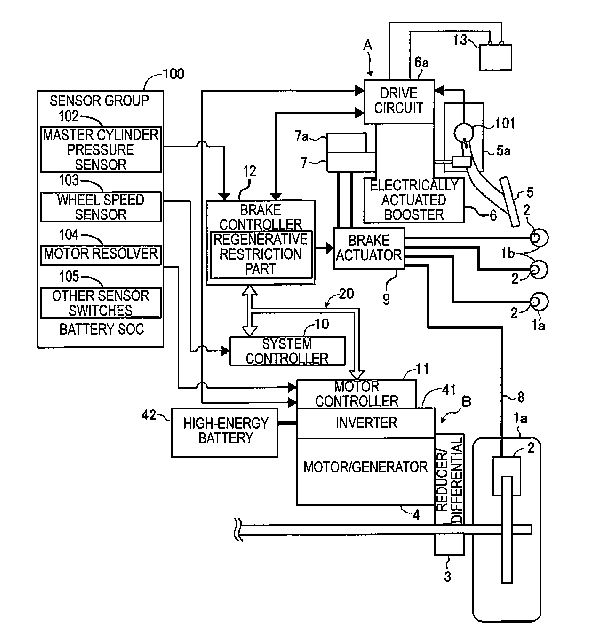
Figure 1 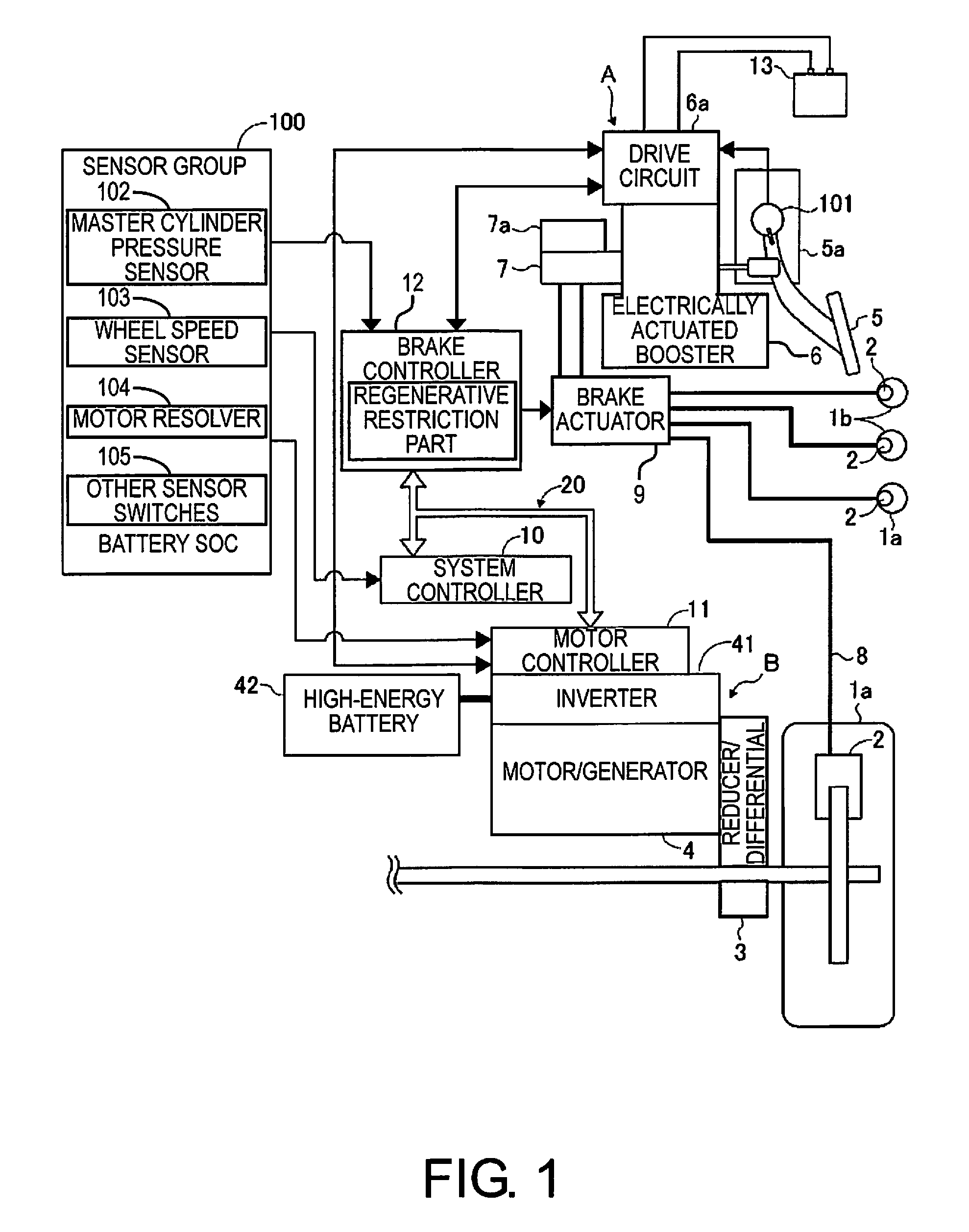
Figure 2 
Figure 3
Abstract
Description
CROSS-REFERENCE TO RELATED APPLICATIONS
[0001] This application is a U.S. National stage application of International Application No. PCT / JP2013 / 055716, filed Mar. 1, 2013, which claims priority to Japanese Patent Application No. 2012-049936 filed in Japan on Mar. 7, 2012, the contents of each of which are hereby incorporated herein by reference.BACKGROUND
[0002] 1. Field of the Invention
[0003] The present invention relates to a braking control device in which a regenerative braking control part carries out regenerative braking only on the front or back drive wheels in a vehicle such as an electric or hybrid car.
[0004] 2. Background Information
[0005] In the past, electrically actuated boost devices have been known in which assisted thrust is provided by an electrically powered actuator to an assist member in accordance with movement of an input member by the brake driver, generating hydraulic brake pressure that has been boosted in a master cylinder (e.g., refer to Japanese Laid-Open Paten...
Examples
embodiment 1
[0028](Embodiment 1)
[0029]First, the configuration of the braking control device of a first embodiment will be described with reference to FIG. 1, which is a system configuration diagram of the braking control device.
[0030]The braking control device of the first embodiment is used in an electric car in which the drive wheels 1a, 1a are driven by a motor / generator 4, the device comprising a hydraulic braking device A, a regenerative braking device B, and a system controller 10.
[0031]First, the hydraulic braking device A will be described. The hydraulic braking device A has a brake pedal 5 that the driver depresses with a foot. The brake hydraulic pressure is generated by a master cylinder 7 in accordance with the depression force on the brake pedal 5. The brake hydraulic pressure generates frictional braking force as a result of being supplied as hydraulic braking force via a brake hydraulic line 8 to a wheel cylinder 2 that is provided on the drive wheels 1a, 1a, and the driven whee...
second embodiment
[0172](Second Embodiment)
[0173]The second embodiment is a modification example of control for the portion that determines the decrease in gradient in the regenerative restriction part for restricting the regenerative braking amount when the wheel speed differential S is larger than the restriction initiation threshold value during regenerative braking. The other aspects of control are the same as in the first embodiment.
[0174]In the second embodiment, as shown in FIG. 10, the master cylinder pressure Pmc that is taken as the friction braking force is read in step S221. The timing of reading of the master cylinder pressure Pmc is at the time when a determination of YES is made in step S4 or is the time at which the process of step S221 is carried out at a subsequent time.
[0175]In the next step S222, the first decrease De1 and the second decrease De2 are calculated based on the master cylinder pressure Pmc that has been read in step S221 and the preset characteristics of the respectiv...
third embodiment
[0180](Third Embodiment)
[0181]The third embodiment is different from the first embodiment in regard to switching from the small restriction phase to the large restriction phase in the calculation process for the regenerative restriction value Tmcom. Specifically, the example is one in which switching from the small regenerative phase to the large regenerative phase is carried out upon detection of a frictional braking force corresponding to the regenerative decrease in accordance with regenerative restriction.
[0182]FIG. 11 is a flow chart showing the flow of processing in the calculation processes for the regenerative restriction value Tmcom during regenerative restriction in the third embodiment.
[0183]In the flow chart, differences with respect to the flow chart of FIG. 4 used in the description of the first embodiment are described.
[0184]In step S102b that is reached after a NO determination in step S101, the switching flag F is set to 0.
[0185]In addition, in step S104b that is re...