

Antenna module and radio communication device
a radio communication device and antenna module technology, applied in loop antennas with ferromagnetic cores, instruments, computing, etc., can solve the problems of difficult to achieve a long communication distance in a direction vertical to the axis of the magnetic core, and difficult to achieve a sufficient communication distan
Patent Information
- Authority / Receiving Office
- US · United States
- Patent Type
- Patents(United States)
- Current Assignee / Owner
- Publication Date
- 2017-02-28
Smart Images
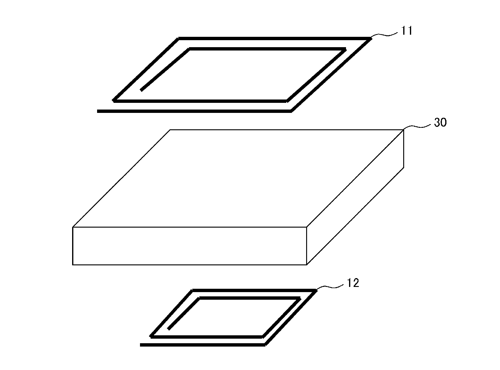
Figure 1 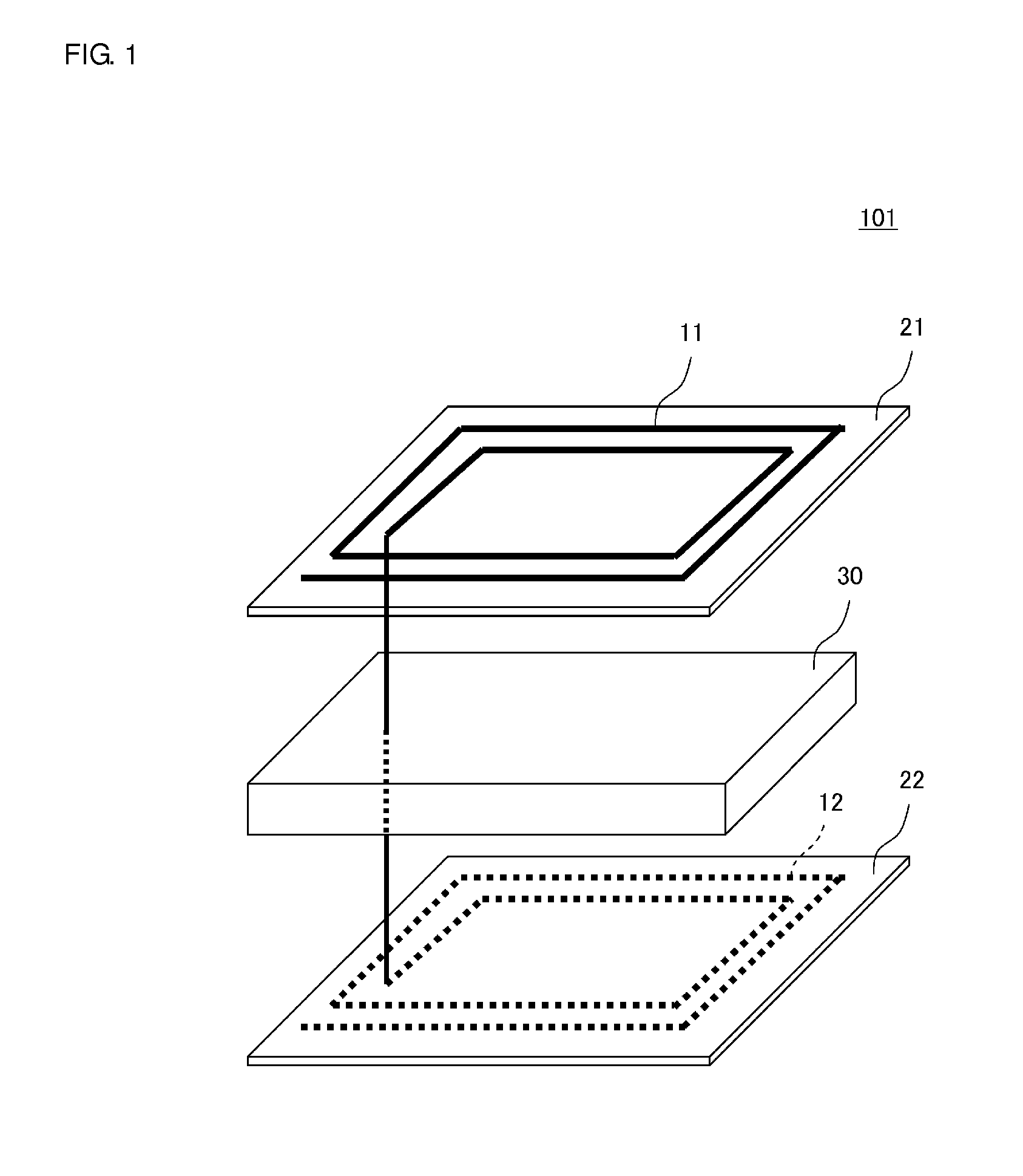
Figure 2 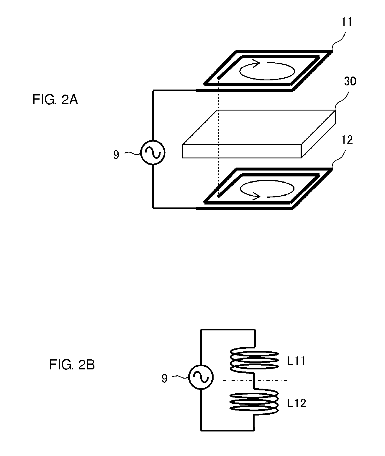
Figure 3
Abstract
Description
BACKGROUND OF THE INVENTION
[0001] 1. Field of the Invention
[0002] The present invention relates to an antenna module and a radio communication device for use in an RFID (Radio Frequency Identification) system or a near field communication (NFC) system.
[0003] 2. Description of the Related Art
[0004] The RFID system is in widespread use as a billing and charge collection system. In the RFID system, a reader and writer and an RFID tag communicate with each other in a non-contact fashion, and communications are performed between these two devices. Each of the reader and writer and the RFID tag includes a RFID chip to process a signal and an antenna to exchange a radio signal. For example, in an HF-band RFID system, a signal is transmitted and received via an induction field between a coil antenna of the reader and writer and a coil antenna of the tag. Japanese Unexamined Patent Application Publication No. 2004-166175, Japanese Patent No. 3933191, and Japanese Unexamined Patent Application Pu...
Examples
first preferred embodiment
[0052]FIG. 1 is an exploded perspective view of an antenna module 101 according to a first preferred embodiment of the present invention. The antenna module 101 is preferably used in an HF-band communication system and includes a first coil conductor 11, a second coil conductor 12 and a magnetic layer 30. The first coil conductor 11 is provided on the top surface of a base body 21 as a non-magnetic sheet. The second coil conductor 12 is provided on the bottom surface of a base body 22 as a non-magnetic sheet.
[0053]More specifically, the first coil conductor 11 and the second coil conductor 12 are formed by patterning, into a coil form, a metal film, such as Cu foil, arranged on the flexible base bodies 21 and 22 made of polyethylene terephthalate or the like. The facing surfaces of the first coil conductor 11 and the second coil conductor 12 are preferably parallel or substantially parallel to each other.
[0054]The magnetic layer 30 may be a ferrite sintered body (ferrite ceramic) th...
second preferred embodiment
[0069]FIG. 5 illustrates a connection arrangement between the first coil conductor 11 and the second coil conductor 12 in an antenna module 102 according to a second preferred embodiment of the present invention. As illustrated in FIG. 5, arrows denote the directions of current. In the first preferred embodiment, the first coil conductor 11 and the second coil conductor 12 preferably are connected in series, while the first coil conductor 11 and the second coil conductor 12 preferably are electrically connected in parallel with each other and then connected to the power supply circuit 9 in the antenna module 102 of the second preferred embodiment. As in the antenna module 101 of the first preferred embodiment, the first coil conductor and the second coil conductor 12 are connected so that the directions of the magnetic fluxes generated around the coil-wound axis direction of the first coil conductor 11 and the second coil conductor 12 are opposite to each other.
[0070]In this way, th...
third preferred embodiment
[0071]FIG. 6A is an exploded perspective view of an antenna module 103. FIG. 6B is a sectional view of the antenna module 103. The antenna module 103 includes the first coil conductor 11, the second coil conductor 12 and the magnetic layer 30. The first coil conductor 11 is provided on the top surface of the magnetic layer 30. The second coil conductor 12 is provided on the top surface of a non-magnetic layer 32. Input and output terminals 51 and 52, and nonreserved mounted terminals 53 and 54 are provided on the bottom surface of the non-magnetic layer 32.
[0072]Non-magnetic layers 31 and 32 are made of dielectric ceramic, and the magnetic layer 30 is made of magnetic ceramic. As illustrated in FIG. 6B, the non-magnetic layers 31 and 32 and the magnetic layer 30 is laminated in a green sheet, and is then integrally sintered.
[0073]In this way, the first coil conductor 11 and the second coil conductor 12 may be combined with the magnetic layer 30 into a unitary body. With this arrange...