
Assembled door pocket frame with adjustable width
An assembly-type, wide-width technology, applied in the direction of window/door frame, etc., to achieve the effect of tight and firm connection, high-end maintenance, and large connection range
Patent Information
- Authority / Receiving Office
- CN · China
- Patent Type
- Applications(China)
- Current Assignee / Owner
- Publication Date
- 2014-07-16
- Estimated Expiration
- Not applicable · inactive patent
Smart Images
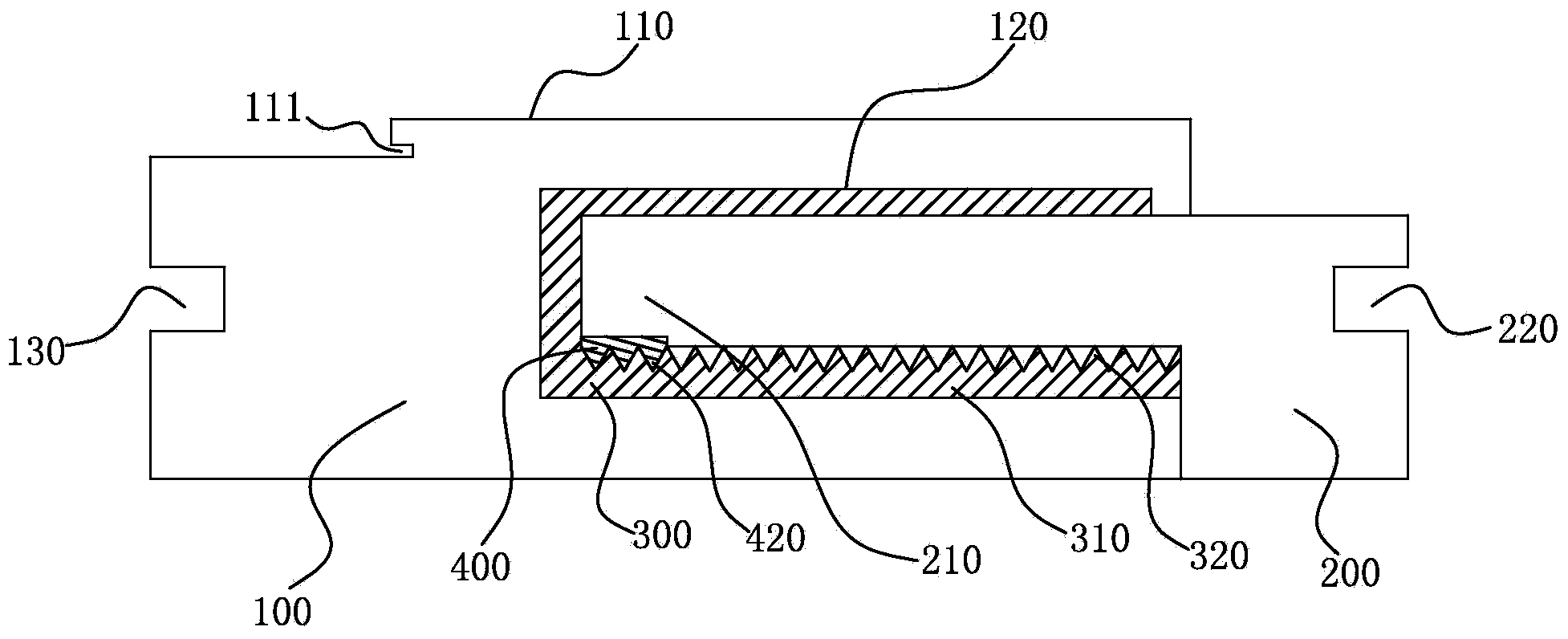
Figure 1 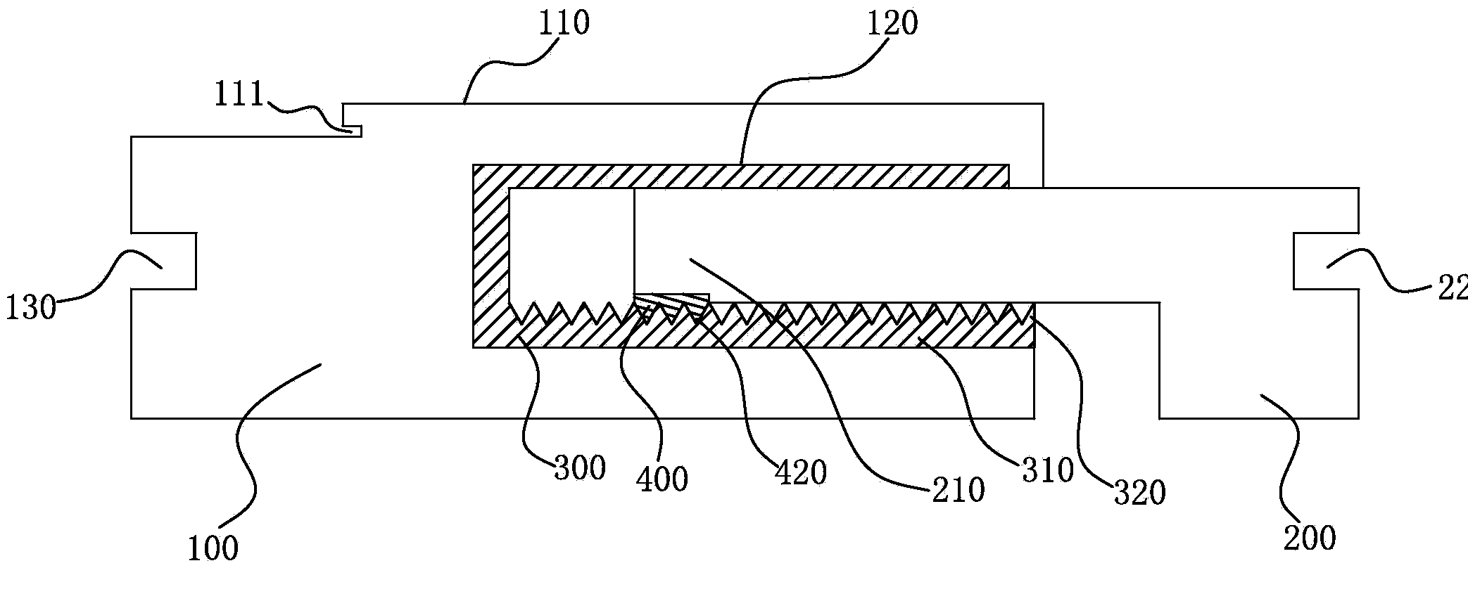
Figure 2 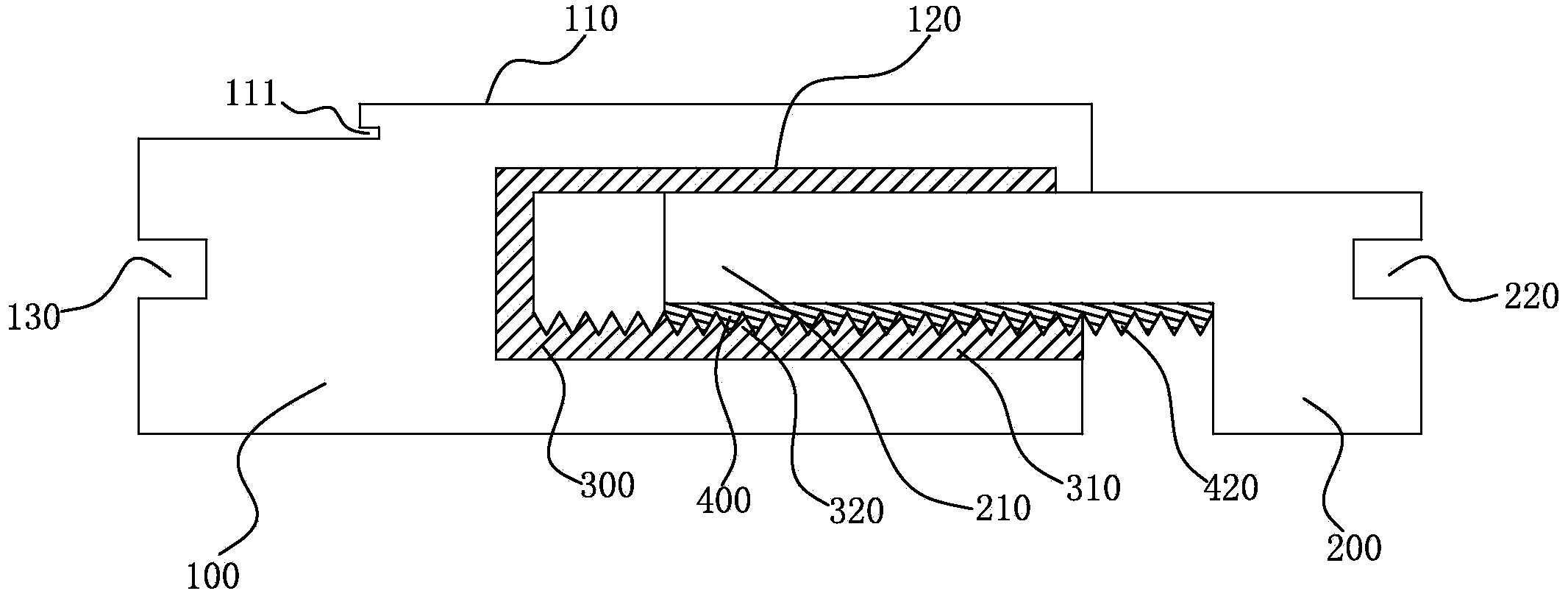
Figure 3
Abstract
Description
Technical field
[0001] The invention belongs to the field of building materials, and relates to a door cover, in particular to an assembled door cover frame with adjustable width. Background technique
[0002] Door cover is a term for architectural decoration, which refers to two door frames inside and outside the door. There are also directly called door frames. It is often used in the decoration and decoration process to protect the door from scratches, corrosion, damage, dirt, etc. It is generally tailor-made, and the basic information of the decoration company is printed on it for advertising. The texture is environmentally friendly and the quality is cheap. .
[0003] If it is the traditional way-the door cover produced on site is directly fixed to the door hole wall by the on-site decorator with nails; and if it is the door cover installation of the complete door product (now more and more users are adopting the complete door product) , We must consider two issues: one is ...
Examples
Embodiment Construction
[0031] The present invention will be further described below through specific embodiments.
[0032] Such as figure 1 , figure 2 , image 3 , Figure 4 with Figure 5 The illustrated assembled door frame with adjustable width includes a main frame 100 and a sub-frame 200 that can be assembled with the main frame 100. A door stop 110 is formed on the main frame 100, and an anti-collision strip is formed on the door stop 110 A fixing groove 111, a U-shaped sub-frame fixing groove 120 is formed on one side of the main frame 100, a line board fixing groove 130 is formed on the other side, and one side of the sub-frame 200 is formed to fit the sub-frame fixing groove 120 A line board fixing groove 220 is formed on the other side of the plug 210, and a U-shaped connecting piece 300 is fixed in the sub-frame fixing groove 120. The opening direction of the U-shaped connecting piece 300 is the same as the opening direction of the U-shaped sub-frame fixing groove 120 A concave-convex struc...