

Intelligent visibility detection equipment for traffic safety monitoring of tunnels
A technology for traffic safety and detection equipment, which is applied in mechanical equipment, lighting and heating equipment, and transmittance measurement. It can solve problems such as hidden dangers in tunnel traffic safety, deviation of detection results, and reduced practicability of visibility detection equipment to increase detection. range effect
Patent Information
- Authority / Receiving Office
- CN · China
- Current Assignee / Owner
- Publication Date
- 2018-01-19
- Estimated Expiration
- Not applicable · inactive patent
Smart Images
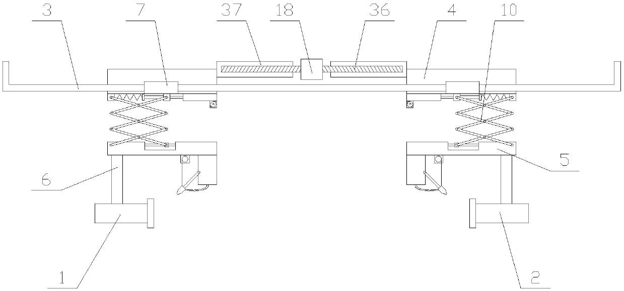
Figure 1 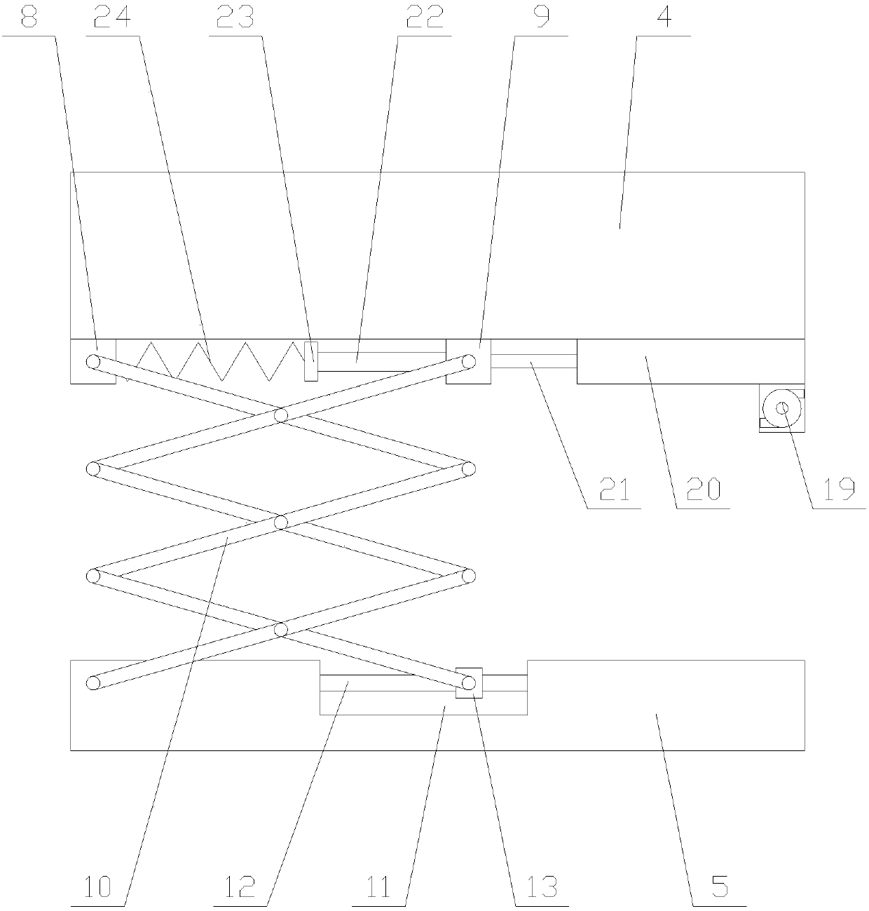
Figure 2 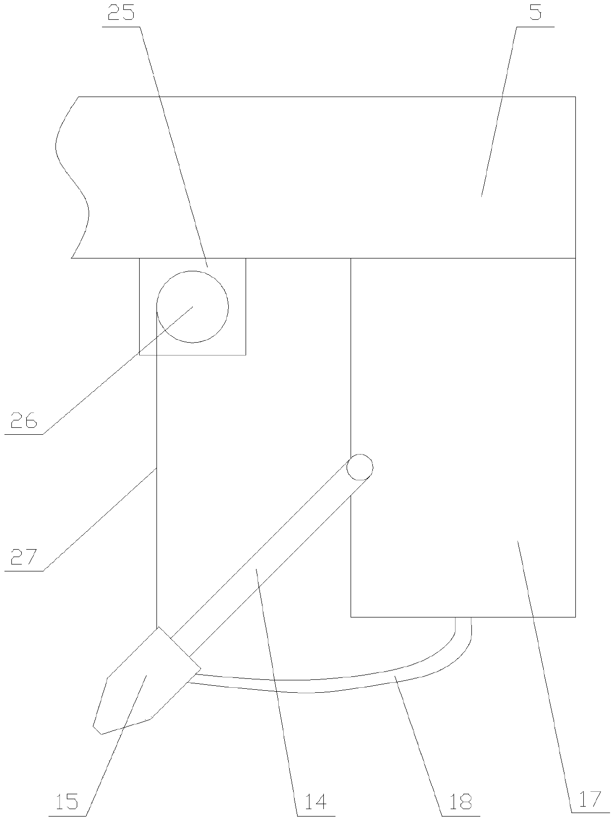
Figure 3
Abstract
Description
technical field
[0001] The invention relates to the field of tunnel monitoring equipment, in particular to an intelligent visibility detection equipment used for tunnel traffic safety monitoring. Background technique
[0002] Visibility, also known as visibility, refers to the maximum distance at which an observer can clearly see an object under normal vision, and is usually equivalent to the "sight distance". Visibility is widely used in surface road tunnels. If the visibility is too low, the driver will easily make mistakes in judging the obstacles and pedestrians ahead, which will affect the intuitive feeling of orientation, positioning, confirmation of distance and speed feeling during driving in the tunnel. In road tunnels, visibility is the main factor that must be considered in normal operation and in fire accidents. At present, people usually use CO / VI detectors to detect the visibility inside the tunnel.
[0003] However, because the existing visibility detection...
Examples
Embodiment Construction
[0027] The present invention is described in further detail now in conjunction with accompanying drawing. These drawings are all simplified schematic diagrams, which only illustrate the basic structure of the present invention in a schematic manner, so they only show the configurations related to the present invention.
[0028] Such as Figure 1-Figure 4 As shown, an intelligent visibility detection device for tunnel traffic safety monitoring includes a telescopic mechanism, a transmitter 1, a receiver 2, two slide rails 3 and two moving mechanisms, the vertical section of the slide rail 3 The shape of the U-shaped section is U-shaped, and the opening of the U-shaped section is upward. The telescopic mechanism is located between two slide rails 3, and the two moving mechanisms are respectively arranged on both sides of the telescopic mechanism. Among the two moving mechanisms, one of them moves The mechanism corresponds to the transmitter 1, and the other moving mechanism cor...