
Fluid-transferring expander
a technology of fluid-transferring expanders and expanders, which is applied in the direction of piston pumps, diaphragm valves, engine diaphragms, etc., can solve the problems of time-consuming and complicated process of tubes of this type of fluid-transferring expanders
Patent Information
- Authority / Receiving Office
- US · United States
- Patent Type
- Patents(United States)
- Current Assignee / Owner
- Publication Date
- 2018-07-31
Smart Images
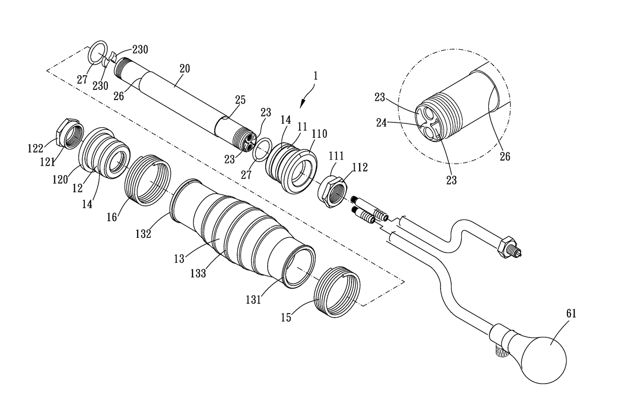
Figure 1 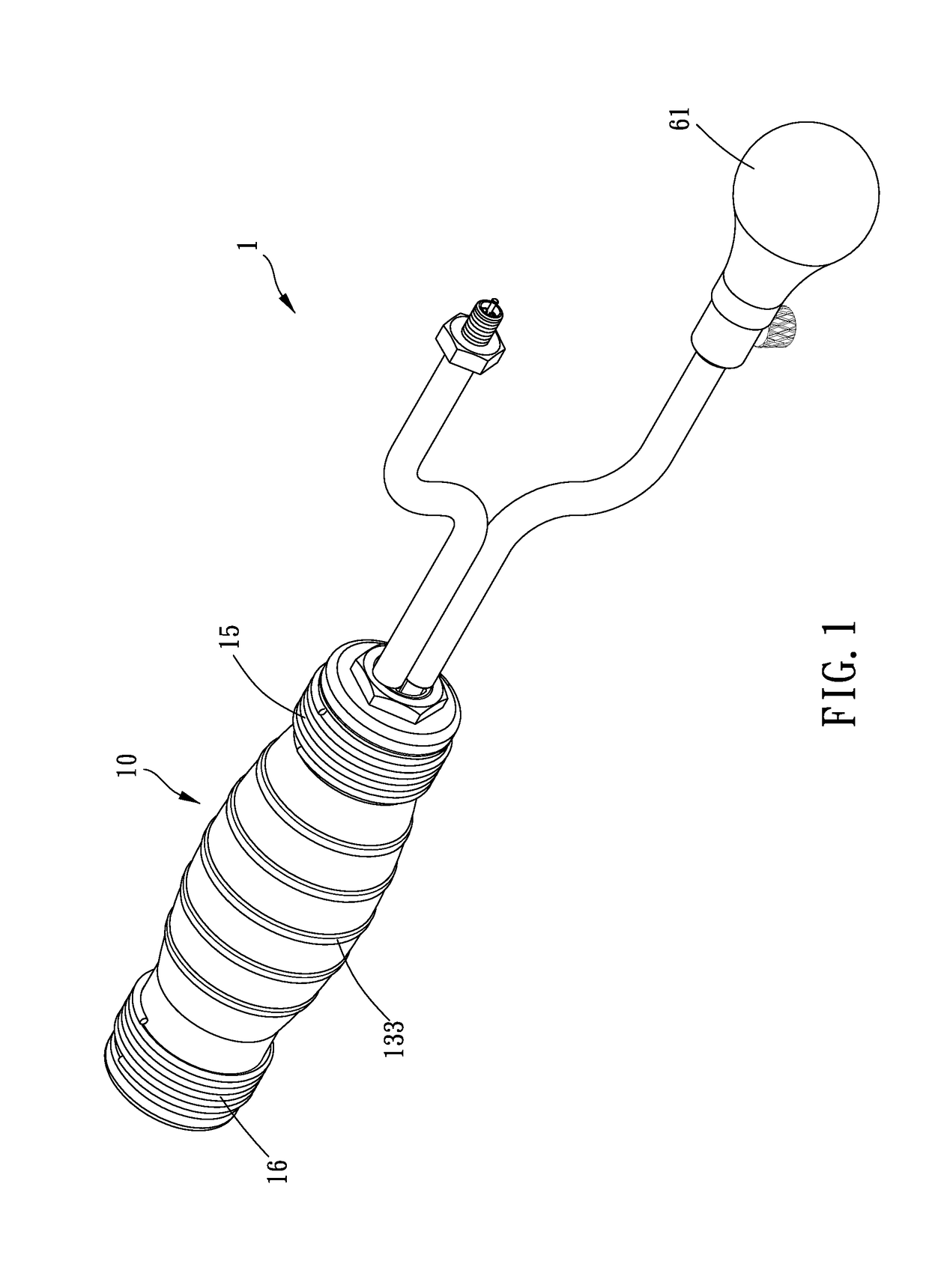
Figure 2 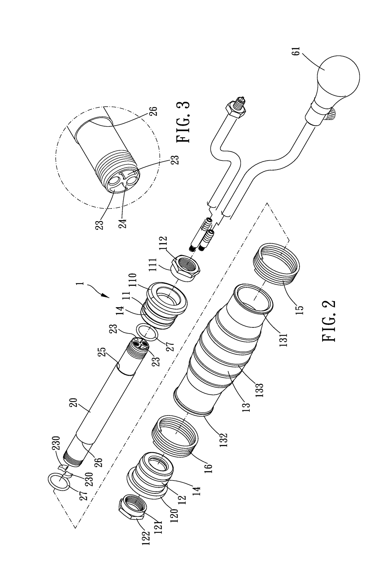
Figure 3
Abstract
Description
BACKGROUND OF THE INVENTION
[0001] Field of the Invention
[0002] The present invention relates to an expander.
[0003] Description of the Prior Art
[0004] In a conventional fluid-transferring expander, an interior of a tube is often formed with additional passages, or a solid tube is further formed with two channels, to connect different fluid sources and make different fluids flow to an expansion bladder or a fluid flow tube respectively. This type of fluid-transferring expanders are disclosed in U.S. Pat. Nos. 5,901,752 and 5,353,842.
[0005] However, it is complicated and time-consuming to process the tube of this type of fluid-transferring expander.
[0006] The present invention has arisen to mitigate and / or obviate the afore-described disadvantages.SUMMARY OF THE INVENTION
[0007] The major object of the present invention is to provide a fluid-transferring expander, wherein a tube is extrudedly and integrally formed. In addition, a bladder portion may be restrained through a spiral spring to pre...
Examples
Embodiment Construction
[0015]The present invention will be clearer from the following description when viewed together with the accompanying drawings, which show, for purpose of illustrations only, the preferred embodiment in accordance with the present invention.
[0016]Please refer to FIGS. 1 to 5, a fluid-transferring expander 1 is provided for transferring a fluid to a fluid flow tube 50, and the fluid-transferring expander 1 includes a bladder structure 10 and a tube 20.
[0017]The tube 20 is disposed through the bladder structure 10, and an expansion space 30 is formed between the tube 20 and the bladder structure 10. Specifically, the bladder structure 10 includes a bladder portion 13, a first sleeve portion 11 and a second sleeve portion 12. The first and second sleeve portions 11, 12 are disposed around the tube 20 and respectively at two ends of the bladder structure 10. The two ends of the bladder portion 13 are fixedly disposed around the first sleeve portion 11 and around the second sleeve portio...