Flooring and method for laying and manufacturing the same

a technology of locking system and floorboard, which is applied in the direction of walls, building components, construction materials, etc., can solve the problems of inability to join the floorboard, inability to lay traditional parquet patterns, and relatively slow manufacturing operation of machining using a shank-end mill, so as to achieve fast and easy joining, advantageous, fast and efficient laying

a technology of locking system and floorboard, which is applied in the direction of walls, building components, construction materials, etc., can solve the problems of inability to join the floorboard, inability to lay traditional parquet patterns, and relatively slow manufacturing operation of machining using a shank-end mill, so as to achieve fast and easy joining, advantageous, fast and efficient laying

US20080028713A1Inactive Publication Date: 2008-02-07VÄLINGE INNOVATION AB

Image

  • Flooring and method for laying and manufacturing the same
  • Flooring and method for laying and manufacturing the same
  • Flooring and method for laying and manufacturing the same

Examples


Embodiment Construction

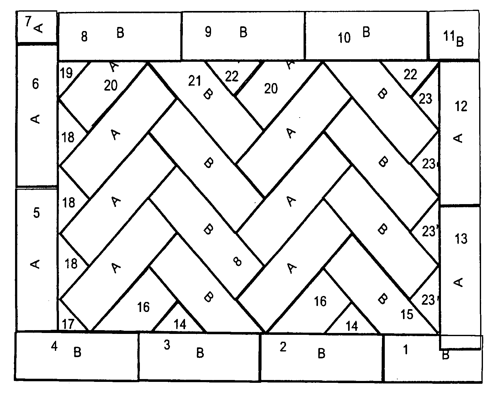
[0047] In the following description, the two types of floorboards according to embodiments of the invention will be designated A and B respectively. This aims merely at illustrating the cooperation between two types of floorboard. Which type of board is designated A and B respectively is immaterial.

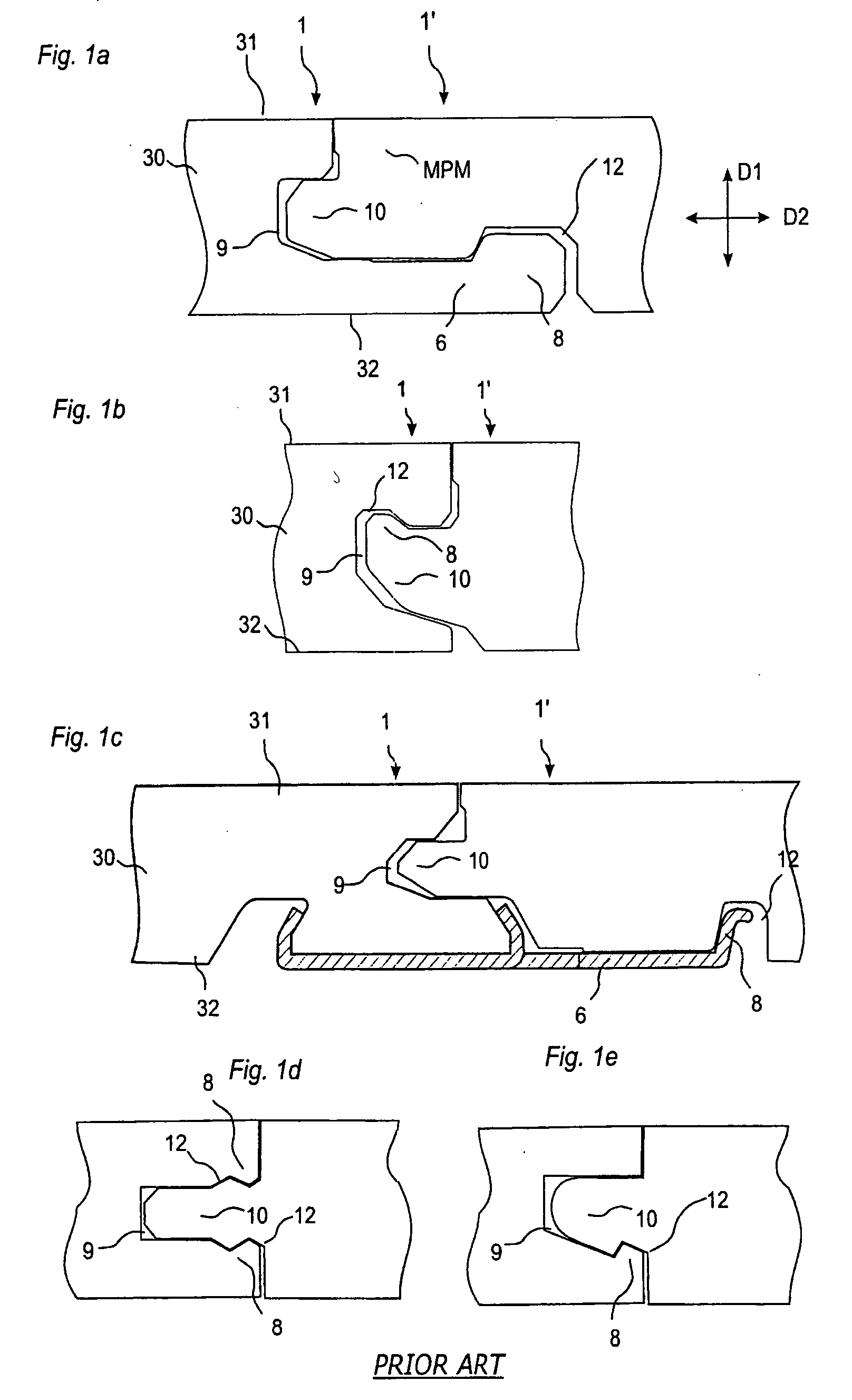
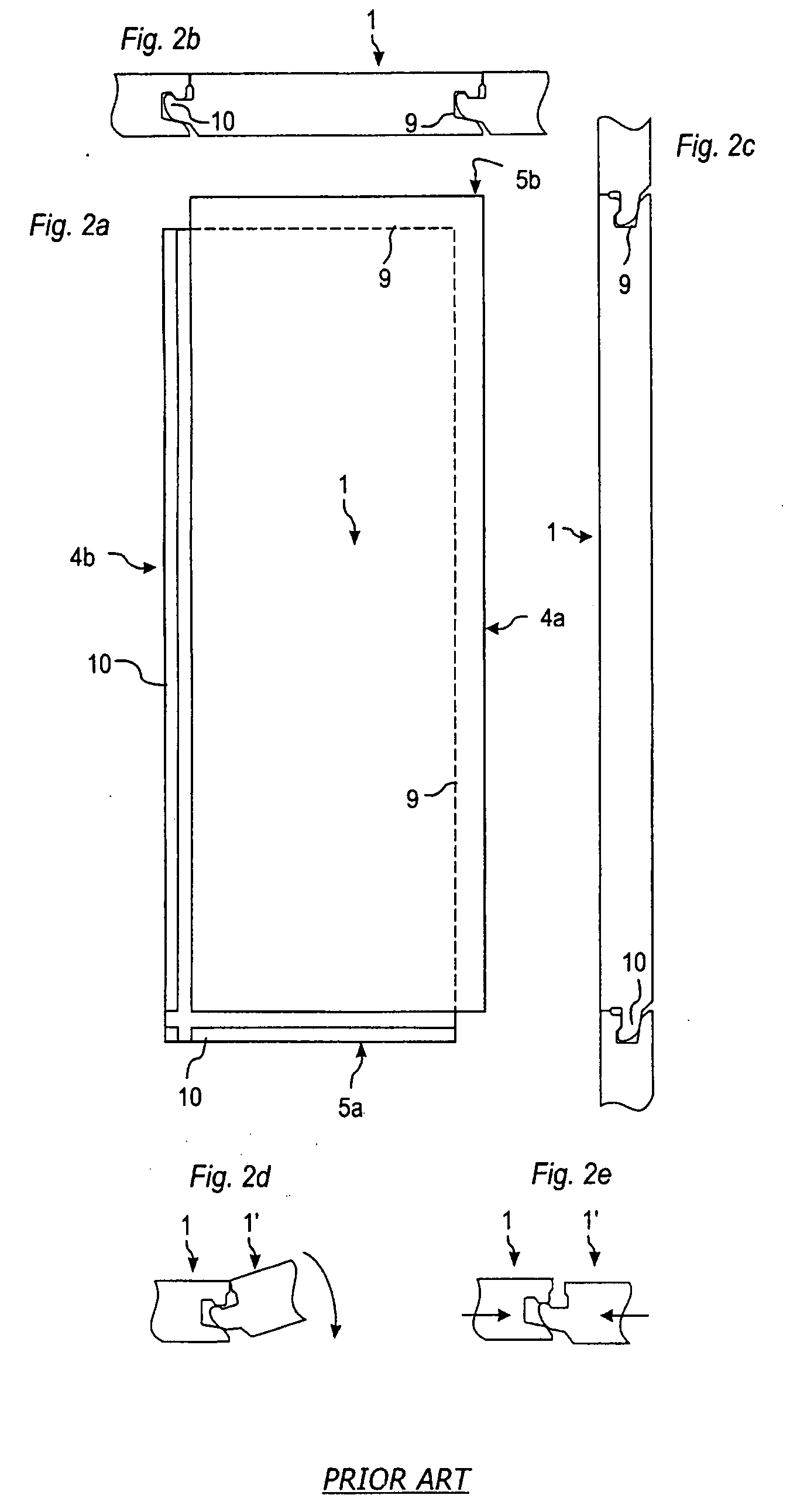
[0048]FIGS. 1a-e illustrate floorboards 1, 1′ with a surface 31, a core 30 and a rear side 32, whose joint edge portions are provided with prior-art mechanical joint systems. The vertical locking means comprise a groove 9 and a tongue 10. The horizontal locking means comprise locking elements 8 which cooperate with locking grooves 12. The joint systems according to FIGS. 1a and 1c have on the rear side 32 a strip 6 which supports or is formed integrally with the locking element 8. The locking systems according to FIGS. 1b, d and e are distinguished by the locking element 8 and the locking groove 12 being formed in the groove / tongue. The locking systems according to FIGS. 1a-1c can be joi...


PUM

PropertyMeasurementUnit
lengthaaaaaaaaaa
lengthaaaaaaaaaa
widthaaaaaaaaaa

Abstract

A flooring includes rectangular floorboards with long sides and short sides, the floorboards being joined in a herringbone pattern, long side to long side and long side to short side, wherein the floorboards have a surface layer of laminate, and the long sides of the floorboards have pairs of opposing mechanical connectors which at least allow locking-together both horizontally and vertically by inward angling.

Description

CROSS REFERENCE TO RELATED APPLICATIONS [0001] The present application is a continuation of U.S. Ser. No. 11 / 380,578, filed Apr. 27, 2006, which is a continuation-in-part of U.S. Ser. No. 10 / 235,940, filed on Sep. 6, 2002, and U.S. Ser. No. 10 / 413,566, filed on Apr. 15, 2003, and claims the priority of SE 0103130-1, filed in Sweden on Sep. 20, 2001 and PCT International Application No. PCT / SE02 / 01731, filed on Sep. 20, 2002, and which designated the United States, and the present application also claims the benefit of U.S. Provisional Application No. 60 / 372,082, filed in the United States on Apr. 15, 2002. PCT International Application No. PCT / SE02 / 01731 and U.S. Provisional Application No. 60 / 372,082 were incorporated by reference into U.S. Ser. No. 10 / 413,566. U.S. Ser. No. 10 / 235,940; U.S. Ser. No. 10 / 413,566; SE 0103130-1; PCT / SE02 / 01731; and U.S. Provisional Application No. 60 / 372,082 are hereby incorporated herein by reference.TECHNICAL FIELD [0002] The invention relates gener...

Claims


Application Information

Patent Timeline
07 Feb 2008
Publication
US20080028713A1
IPC
E04F15/00; E04F15/02; E04F15/04
CPC
E04C2/20; E04F15/02; E04F15/02033; E04F15/04; E04F2201/0115; E04F2201/0153; Y10T29/49; E04F2201/026
Inventors
PERVAN, DARKO; PERVAN, TONY