
Magnetic stop mechanism in portable lifting device
A technology of stopping mechanism and lifting device, which is applied to the parts of the instrument and the direction of the instrument, can solve the problems such as difficult to lock, and achieve the effect of reliable stopping function
Patent Information
- Authority / Receiving Office
- CN · China
- Patent Type
- Patents(China)
- Current Assignee / Owner
- Publication Date
- 2012-05-23
- Estimated Expiration
- Not applicable · inactive patent
Smart Images
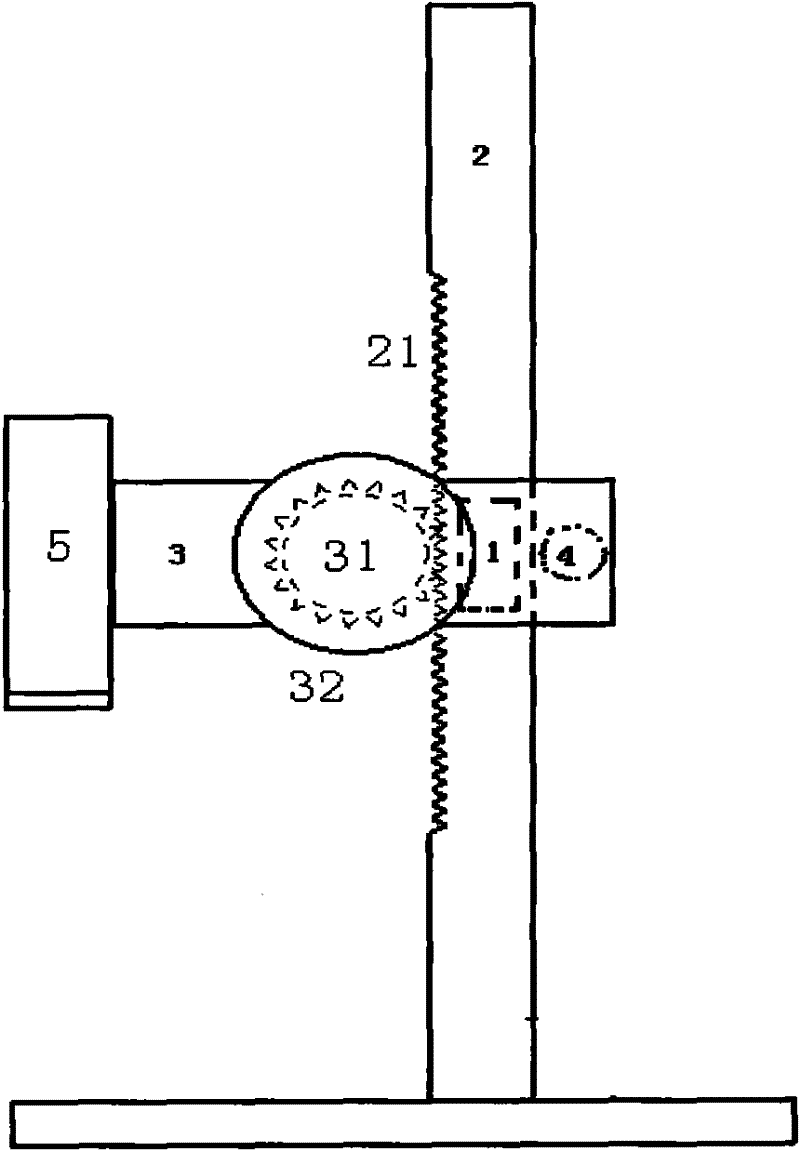
Figure 1 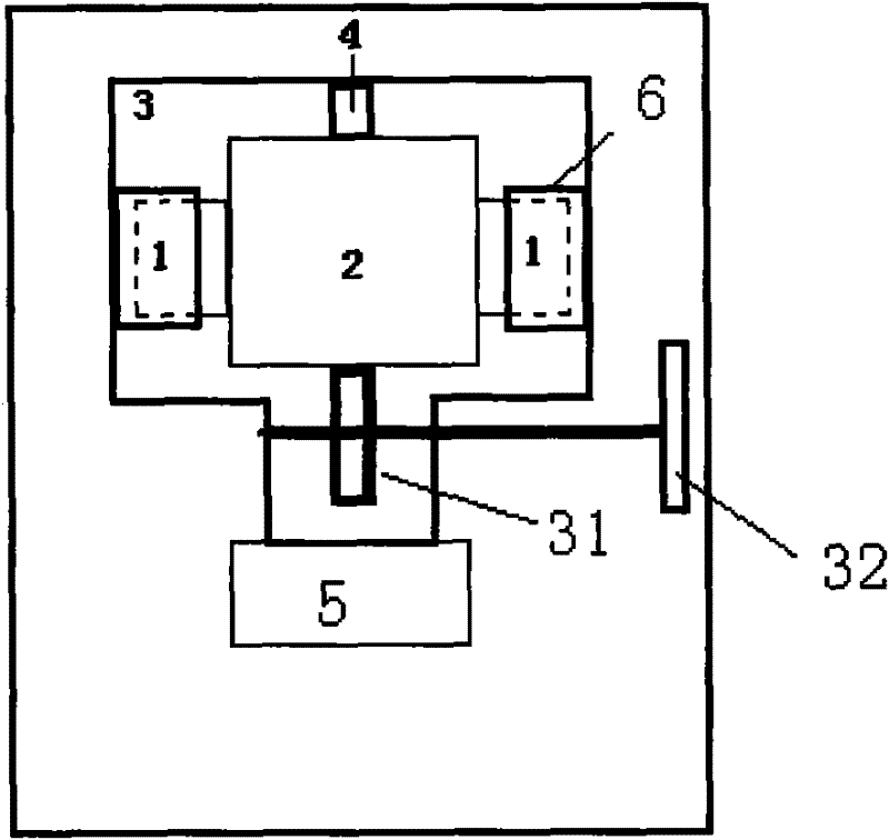
Figure 2 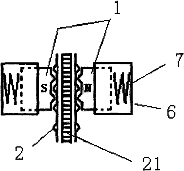
Figure 3
Abstract
Description
technical field
[0001] The invention relates to a stop mechanism, in particular to a magnetic stop mechanism in a lightweight lifting device. Background technique
[0002] In some precise and lightweight lifting devices, it is necessary to move freely, accurately locate, and require a reliable stop to avoid sliding and shifting. For example, the lifting of the microscope lens barrel, the lifting of the lens of the magnifying machine, the lifting of the heat source in the metal specific heat measurement device, etc., all use the lifting device.
[0003] Under the action of external force, the gear in the lifting device rolls on the rack to drive the load to move up and down. If there is no stop mechanism or the stop mechanism cannot generate enough force against the load and the gravity of the movable part itself, once the external force is removed, under the action of gravity, the gear must drive the movable part and load in the lifting device to slide down the rack . [...
Examples
Embodiment Construction
[0021] A kind of magnetic stop mechanism in the lightweight lifting device of the present invention, see figure 1 with figure 2 , the magnetic stop mechanism includes a strong magnetic slider group 1, a sliding guide rail 2, a movable part with hanging ears 3 and an adjusting roller 4. The ferromagnetic slider group 1 is two ferromagnetic sliders, the N and S poles of the pair of ferromagnetic sliders face each other across the sliding guide rail 2 and are adsorbed on both sides of the sliding guide rail 2 . The strong magnetic slider 1 is embedded in the movable part 3 with hanging ears, and a spring 7 is arranged between the strong magnetic slider 1 and the hanging ears 6 to keep an appropriate activity margin; There is a gear 31 adapted to the rack 21, and a rotary handle 32 for rotating the gear 31. The load 5 is connected with the movable part 3 with hanging ears. The movable part with hanging lugs pushes the magnetic slider to move up and down along the sliding guide...