
Water pocket using a percolation well for the in-ground storage of percolated rainwater
A technology of seepage pipes and rainwater, which is applied in waterway systems, sewage removal, water supply devices, etc., can solve problems such as inability to remove, rainwater infiltration, and infiltration, and achieve the effect of easy and sustainable management.
Patent Information
- Authority / Receiving Office
- CN · China
- Patent Type
- Applications(China)
- Current Assignee / Owner
- Publication Date
- 2011-07-27
- Estimated Expiration
- Not applicable · inactive patent
Smart Images
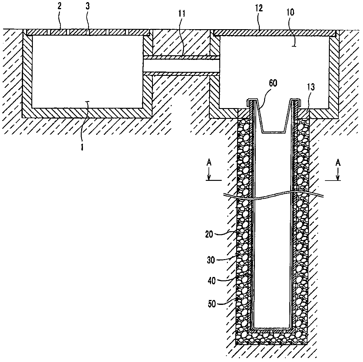
Figure 1 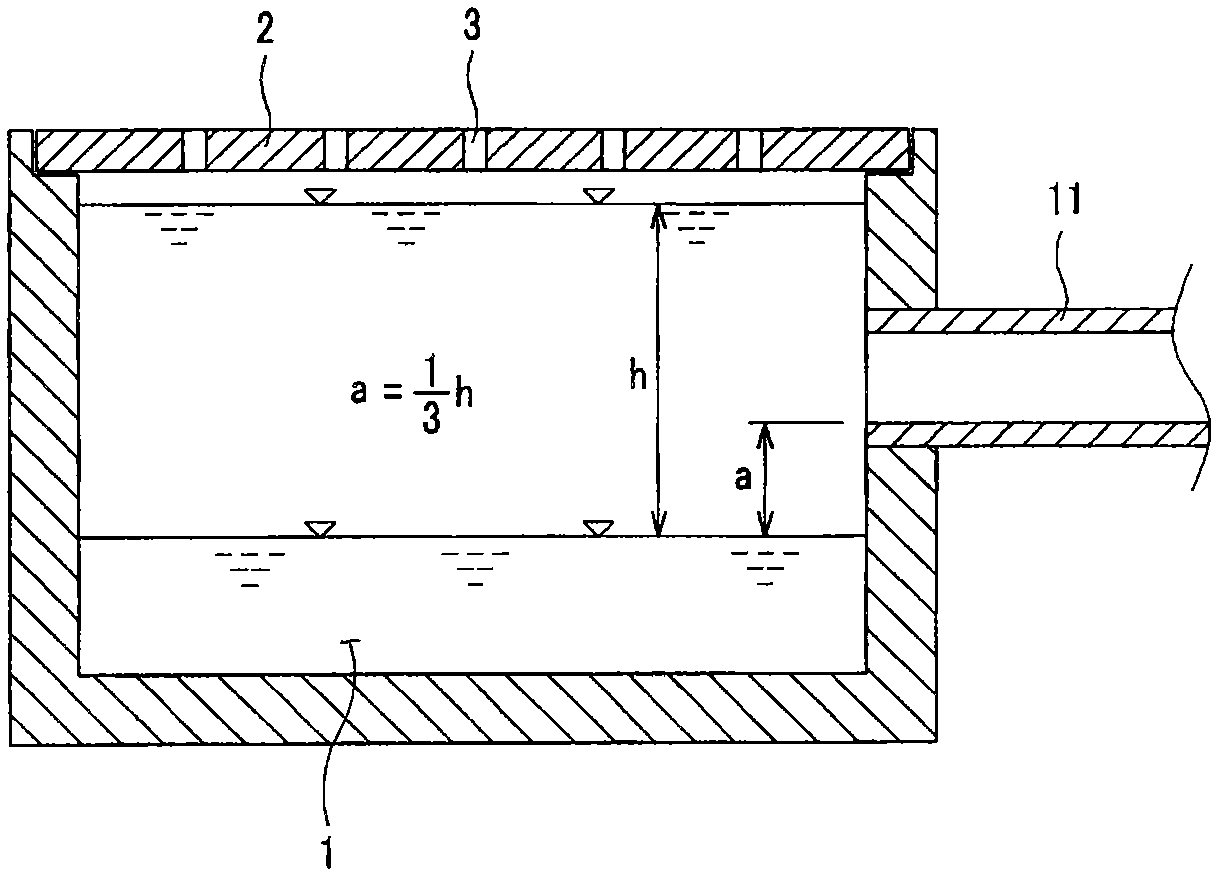
Figure 2 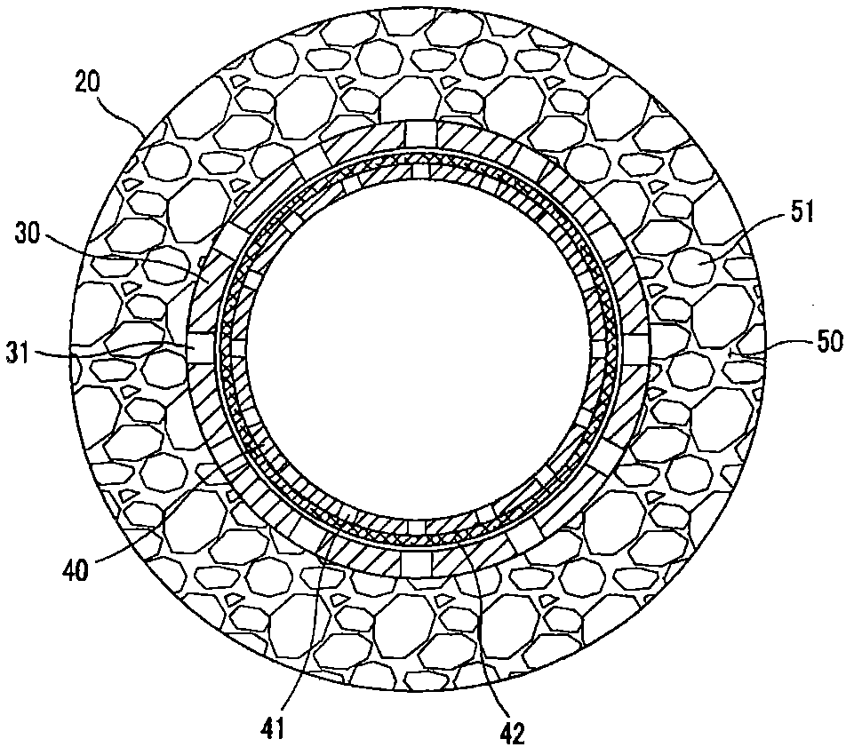
Figure 3
Abstract
Description
technical field
[0001] The present invention relates to the water bag (Water Pocket) that adopts the permeable pipe well that infiltrates and stores rainwater into the soil. Rainwater is infiltrated and stored in the soil, thereby slowing down the outflow of rainwater and preventing the flooding of the river, using the water bladder of the seepage pipe well that infiltrates and stores rainwater in the soil. Background technique
[0002] Recently, cities, especially low-lying areas, often suffer from unpredictable flood disasters due to frequent torrential rains or heavy rains during the rainy season or typhoons. One of the main reasons for causing rain floods or large amounts of water in low-lying areas of the city is that the drainage function of rivers or sewers is not perfect, causing rainwater to overflow beyond urban drainage facilities, resulting in flooding of low-lying areas and rivers.
[0003] Recently, due to the development of industrialization, most roads in ci...
Examples
Embodiment Construction
[0025] The present invention and the technical problems achieved by implementing the present invention become clear from the description of the following preferred embodiments. The following examples are just to illustrate the present invention, but not to limit the scope of the present invention. The present invention will be described in detail below with reference to the accompanying drawings.
[0026] figure 1 It is a longitudinal sectional view of the water bag provided by the embodiment of the present invention, figure 2 It is an enlarged cross-sectional view of the detailed structure of the connecting pipe provided by the embodiment of the present invention, image 3 yes figure 1 The A-A section diagram, Figure 4 It is an enlarged cross-sectional view of the detailed structure of the seepage tube well provided by the embodiment of the present invention.
[0027] As shown in the embodiments of the present invention, the water bladder provided by the present invent...