
Gear rack type self-locking rope clip
A rack-and-pinion and cable-holding device technology, which is applied in the field of automobile crash test devices, can solve problems such as troublesome operation, complex structure, and small locking force
Patent Information
- Authority / Receiving Office
- CN · China
- Patent Type
- Applications(China)
- Current Assignee / Owner
- Publication Date
- 2012-01-18
- Estimated Expiration
- Not applicable · inactive patent
Smart Images
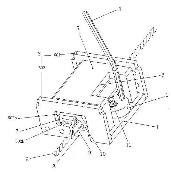
Figure 1 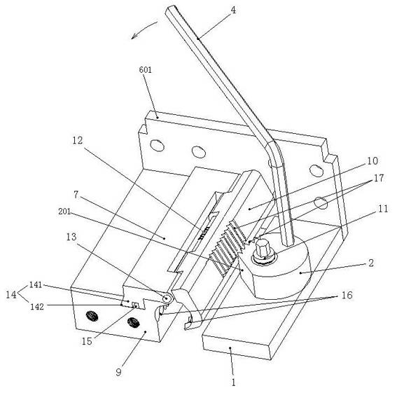
Figure 2 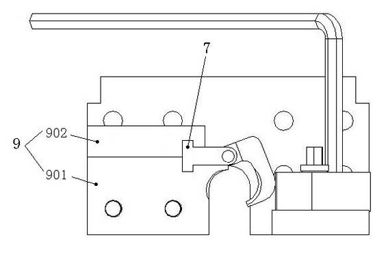
Figure 3
Abstract
Description
technical field
[0001] The invention belongs to an automobile collision test device, in particular to a rack and pinion self-locking gripping device. Background technique
[0002] At present, the grips used in domestic automobile crash tests can be divided into two types: fixed type and trailer type; fixed type grips are always connected with the traction rope from the beginning to the end of the collision test, which cannot realize the cycle of the collision line, and the operation is troublesome . Moreover, the tension between the fixed rope grip and the traction rope is too large at the moment of collision, which is easy to cause accidents; for the traditional tow-type grip rope, the collision line can be realized, but its structure is complicated, and the grip force is also affected by its structure. In the currently known locking methods, the eccentric cam locking method is widely used in various locking mechanisms due to its simple structure, fast locking and self-loc...
Examples
Embodiment 1
[0015] See figure 1 , figure 2 , the rack and pinion type self-locking grip rope device, including a base, the base includes a left base 9 and a right base 1, and the left and right bases 9, 1 are connected together to form an integral connection plate 6; the connection plate 6 is divided into upper and lower connections Plates 601, 602; a through opening A is formed between the left and right bases 9 and 1 bottoms, and the left base 9 on one side along the direction of the through opening A is provided with a hinge slider 7 sliding in this direction; the hinge slider 7 and The left base 9 is connected by a dovetail rail chute structure 14, the left base 9 is provided with a dovetail groove 14, and the bottom of the hinge slider 7 is provided with a dovetail slide rail 141 to cooperate with the dovetail groove 141 on the left base 9; the hinge slider The dovetail slide rail 141 of 7 is provided with a limit hole 15; the hinge slider 7 is hinged with a long pin 13 to have a m...