
Magnetic force controlled ink permeating type micro-contact printing device
A technology of micro-contact printing and magnetic force control, applied in printing, stamping, etc., can solve the problems of difficult printing of large-area patterns, time-consuming and labor-consuming stamps, and limited size of elastic stamps, and achieve continuous ink filling and saving usage. Effect
Patent Information
- Authority / Receiving Office
- CN · China
- Patent Type
- Patents(China)
- Current Assignee / Owner
- Publication Date
- 2014-01-29
- Estimated Expiration
- Not applicable · inactive patent
Smart Images
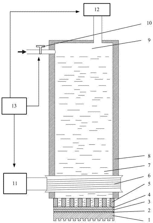
Figure 1 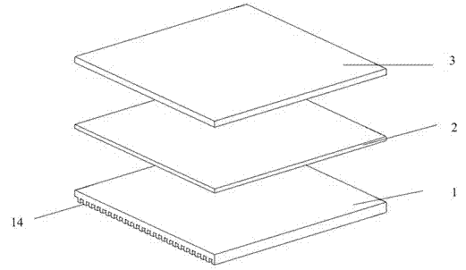
Figure 2 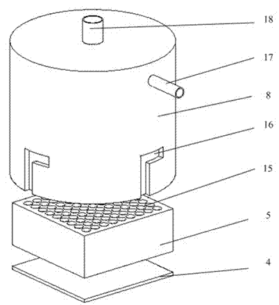
Figure 3
Abstract
Description
technical field
[0001] The invention relates to a printing device, in particular to a magnetically controlled ink permeable micro-contact printing device capable of forming micro-nano patterns on a specific substrate. Background technique
[0002] Microcontact printing technology is to contact the elastic stamp with micro-nano pattern on the surface with the surface of the substrate to form a patterned self-assembled monomolecular layer. It is different from other printing methods in that it uses a self-assembly system to form micropatterns of different materials. and microstructure.
[0003] The specific process of microcontact printing is to first use photolithography, electron beam etching, precision machining, etc. to form the required pattern on the surface of a silicon wafer to form a master plate for casting elastic stamps. Then polydimethylsiloxane is cast into the master plate, and after curing, it is peeled off to obtain an elastic stamp with micropatterns on the ...
Examples
Embodiment Construction
[0024] The present invention will be further described below in conjunction with drawings and embodiments.
[0025] Such as figure 1 , image 3 , Figure 4 As shown, the present invention includes a pattern layer 1, a magnetically sensitive layer 2, a sealing layer 3, a permeable layer 4, a support layer 5, a coil sleeve 19, an ink tank 8, and an electromagnetic flow valve 10; the lower end surface of the pattern layer 1 has a pattern, and the pattern The upper end surface of the layer 1 is provided with a magnetic sensitive layer 2, a sealing layer 3, a permeable layer 4, a support layer 5 and a cylindrical ink tank 8 in sequence; a coil sleeve 19 is provided on the cylindrical surface of the ink tank 8 near the end of the support layer 5 The ink feed pipe 17 on the ink tank 8 cylindrical surface away from the support layer 5 is provided with an electromagnetic flow valve 10; the top surface of the ink tank 8 is provided with a pneumatic communication pipe 18; the coil and ...